Non Alloy Tubes
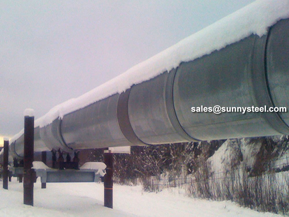
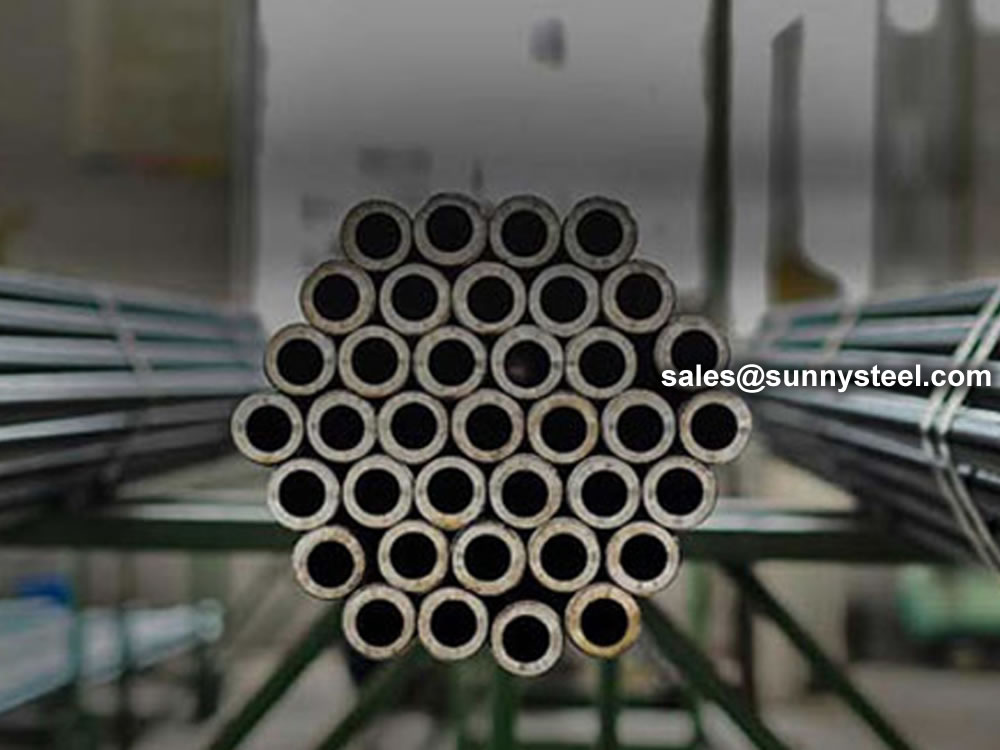
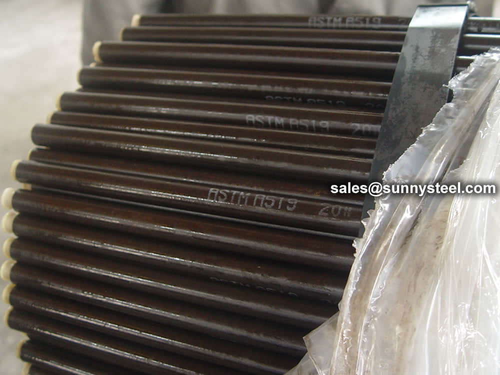
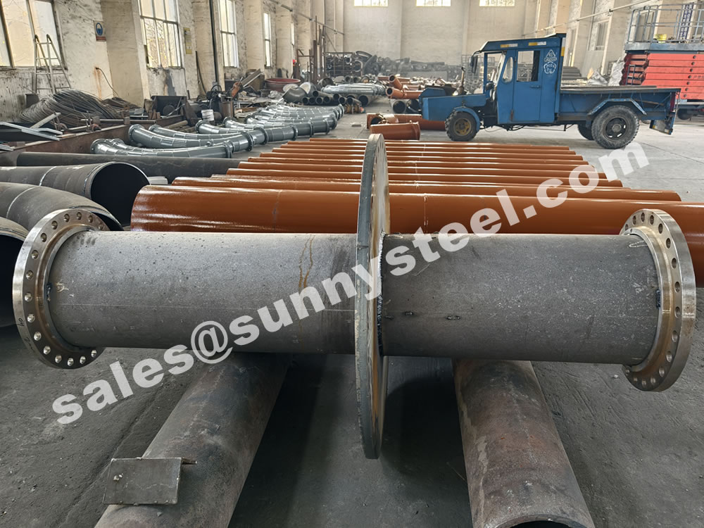
Seamless Carbon Steel Tubes
EN 10216-2 Seamless steel tubes for pressure purposes —Technical delivery conditions Part 2: Non-alloy and alloy steel tubes with specified elevated temperature properties
Download PDF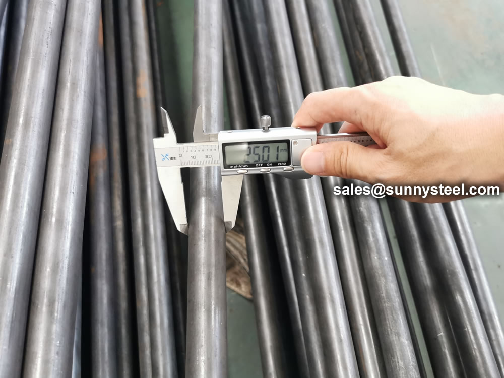
This Part of EN 10216 specifies the technical delivery conditions in two test categories for seamless tubes of circular cross section, with specified elevated temperature properties, made of non-alloy and:alloy steel.
NOTE This Part of EN 10216 may also be applied for tubes of non-circular cross section; necessary modification should be agreed a the time of enquiry and order.
This European Standard incorporates by date or undated reference, provisions from other publications. These normative references are cited at the appropriate places in the text and the publications are listed hereafter. For date references, subsequent amendments to or revisions of, any of these publications apply to this European Standard only when incorporated in it by amendment or revision. For undated references the latest edition of the publication referred to applies (including amendments).
The requirements of this European Standard rule when they differ from those in the standards and documents referred to below:
EN 10002-1, Metallic materials - Tensile testing - Part 1: Method of test (at ambient temperature).
EN 10002-5, Metallic materials - Tensile testing - Part 5: Method of testing (at elevated temperature).
EN 10020, Definitions and classification of grades of steel.
EN 10021, General technical delivery requirements for steel and iron products.
EN 10027-1, Designation systems for steels - Part 1 : Steel names, principle symbols. .
EN 10027-2, Designation systems for steels - Part 2: Numerical systems.
EN 10045-1, Metallic materials - Charpy impact test - Part 1: Test method.
EN 10052, Vocabulary of heat treatment terms for ferrous products.
EN 10204, Metallic products - Types of inspection documents.
ENV 10220, Seamless and welded steel tubes - Dimensions and masses per unit length
EN 10233, Metallic materials - Tubes - Flattening test.
EN 10234, Metallic materials - Tubes - Drift expanding test.
EN 10236, Metallic materials - Tubes - Ring expanding test.
EN 10237, Metallic materials - Tubes - Ring tensile test.
EN 10246-1, Non-Destructive Testing of steel tubes Part 1 : Automatic electromagnetic testing of seamless and welded (except submerged arc welded) ferromagnetic steel tubes for verification of hydraulic leak-tightness.
EN 10246-5,Non-Destructive Testing of steel tubes – Part 5: Automatic full peripheral magnetic transducer/flux leakage testing of seamless and welded (except submerged arc-welded) ferromagnetic steel tubes for the detection of longitudinal imperfections.
EN 10246-6, Non-Destructive Testing of steel tubes - Part 6: Automatic full peripheral ultrasonic testing of seamless steel tubes for the detection of transverse imperfections.
EN 10246-7, Non-Destructive Testing of steel tubes - Part 7 : Automatic full peripheral ultrasonic testing of seamless and welded (except submerged arc welded) steel tubes for the detection of longitudinal imperfections.
EN 10246-14,Non-Destructive Testing of steel tubes - Part 14:Automatic ultrasonic testing of seamless and welded (except submerged arc welded) steel tubes for the detection of laminar imperfections.
EN 10256, Non-Destructive Testing of steel tubes - Qualification and competence of level 1 and level 2 NDT personnel.
EN ISO 377, Steel and steel products - Location and preparation of samples and test pieces for mechanical testing (ISO 377:1997)
prEN 10168 1), Iron and steel products - Inspection documents - List of information and description.prEN 10266 1) ,Steel tubes, fittings and structural hollow sections - Symbols and definition of terms for use in product standards
EN ISO 2566-1, Steel - Conversion of elongation values – Part 1: Carbon and low-alloy steels (ISO 2566-1:1984)
ISO 14284, Steel and iron - Sampling and preparation of samples for the determination of chemical composition
CR 10260, Designation systems for steel - Additional symbols
CR 10261, ECISS Information Circular IC 11 - Iron and steel - Review of available methods of chemical analysis.
For the purposes of this Part of EN 10216, the terms and definitions given in EN 10020, EN 10021, EN 10052 and prEN 10266 and the following apply:
3.1
test category
classification that indicates the extent and level of inspection and testing
3.2
employer
organisation for which a person works on a regular basis.
NOTE The employer may be either the tube manufacturer or supplier or a third party organisation providing, Non-Destructive Testing (NDT) services.
For the purpose of this Part of EN 10216, the symbols given in prEN 10266 and the following apply:
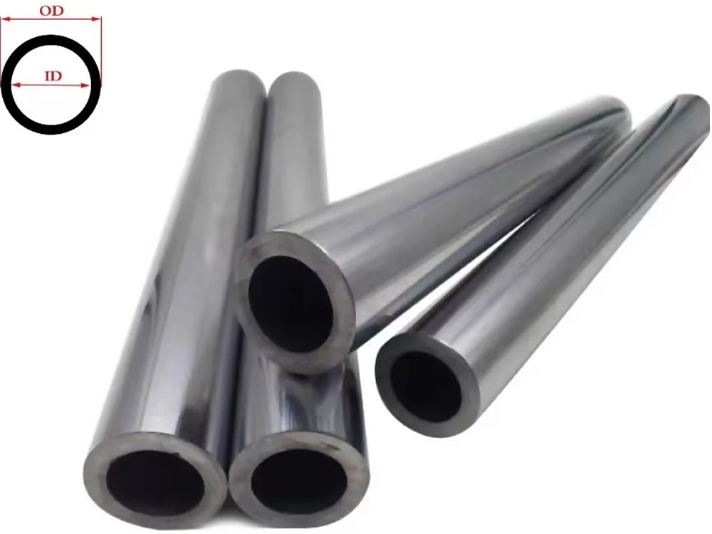
d specified inside diameter;
d min specified minimum inside diameter;
T min specified minimum wall thickness;
D c calculated outside diameter;
d c calculated inside diameter;
1) In preparation; until this document is published as a European Standard, the corresponding national standard(s) should be agreed at the time of enquiry and order.
T c calculated wall thickness;
TC test category
5.1 Classification
In accordance with the classification system in EN 10020, the steel grades P195GH, P235GH and P265GH are classified as non-alloy quality steels and the other steel grades are classified as alloy special steels.
5.2 Designation
5.2.1 For the tubes covered by this Part of EN 10216 the steel designation consists of:
the number of this Part of EN 10216;plus either:
the steel name in accordance with EN 10027-1 and CR 10260;
or:the steel number allocated in accordance with EN 10027-2.
5.2.2 The steel name of non-alloy steel grades is designated by:
the capital letter P for pressure purposes;
the indication of the specified minimum yield strength at room temperature for wall thickness less than or equal to 16 mm, expressed in MPa ( see Table 4):
the symbols GH for elevated temperature.
5.2.3 The steel name of alloy steel grades is designated by the chemical composition (see Table 2) and the symbols for the heat treatment, where specified in column 3 and footnote 3 of Table
6.1 Mandatory information
The following information shall be supplied by the purchaser at the time of enquiry and order:
a) the quantity (mass or total length or number);
b) the term "tube";
c) the dimensions (outside diameter D and wall thickness T or a set of dimensions covered by Option 11) (seeTable 6);
d) the designation of the steel grade in accordance with this Part of EN 10216 (see 5.2);
e) the test category for non-alloy steel (see 9.3).
6.2 Options
A number of options are specified in this Part of EN 10216 and these are listed below. In the event that the purchaser does not indicate a wish to implement any of these options at the time of enquiry and order, the tubes shall be supplied in accordance with the basic specification (see 6.1).
1) Cold finishing (see 7.3.2).
2) Restriction on copper and tin content (see Table 2).
3) Product analysis (see 8.2.2).
4) Impact testing (see Table 4).
5) Longitudinal impact testing at -10° C for non-alloy steel grades (see Table 4).
6) Tensile testing at elevated temperature (see 8.3.2).
7) Selection of leak-tightness test method (see 8.4.2.1).
8) Non-Destructive Testing for test category 2 tubes for detection of transverse imperfections (see 8.4.2.2).
9) Non-Destructive Testing for test category 2 tubes for detection of laminar imperfections (see 8.4.2.2).
10) Special ends preparation (see 8.6).
11) Set of dimensions other than D and T (see 8.7.1).
12) Exact lengths (see 8.7.3).
13) The type of inspection document other than the standard document (see 9.2.1).
14) Test pressure for hydrostatic leak-tightness test (see 11.8.1).
15) Wall thickness measurement away from the ends (see 11.9).
16) Non-Destructive Testing method (see 11.11.1).
17) Additional marking (see 12.2).
18) Protection (see 13).
6.3 Examples of an order
6.3.1 Example 1
100 t of seamless tube with an outside diameter of 168,3 mm, a wall thickness of 4,5 mm, in accordance with EN 10216-2, made of steel grade P265GH, to test category 1 with a 3.1.C inspection certificate in accordance with EN 10204:
100 t - Tube - 168,3 x 4,5 - EN 10216-2 - P265GH - TC1 - Option 13: 3.1.C
6.3.2 Example 2
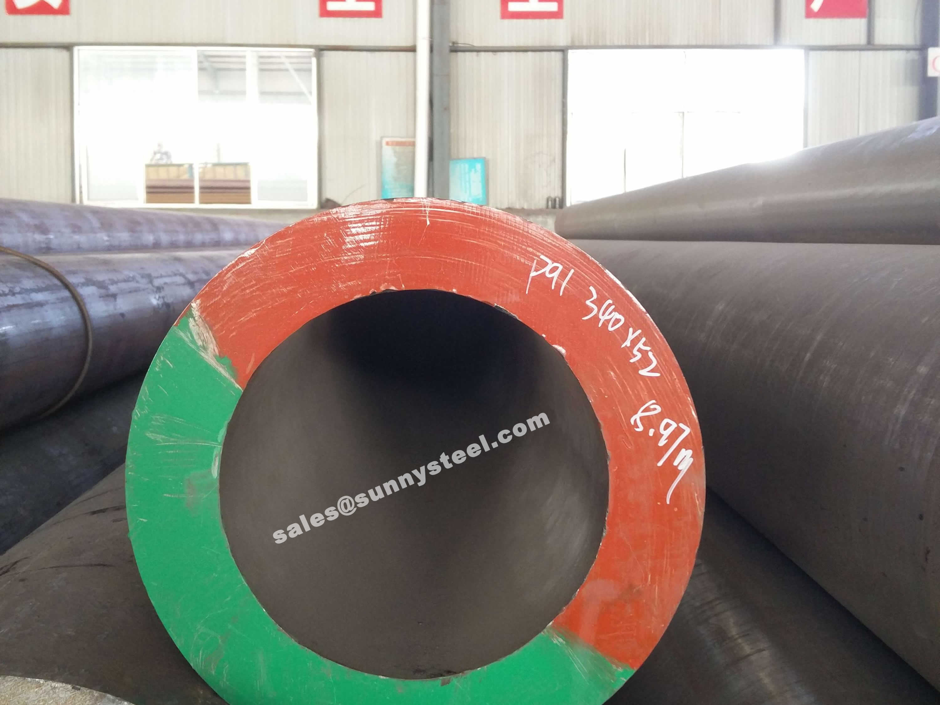
100 m of seamless tube with a minimum inside diameter of 240 mm, a minimum wall thickness of 40 mm in accordance with Part of EN 10216, made of steel grade 10CrMo9-10, with a 3.1.C inspection certificate in accordance with EN 10204:
100 m - Tube - d min 240 x T min 40 - EN 10216-2 - 10CrMo9-10 - Option 13: 3.1.C
7.1 Steel making process
The steel making process is at the discretion of the manufacturer.
7.2 Deoxidation process
Steels shall be fully killed.
7.3 Tube manufacture and delivery conditions
7.3.1 All NDT activities shall be carried out by qualified and competent level 1,2 and/or 3 personnel authorised to operate by the employer.
The qualification shall be in accordance with EN 10256 or, at least, an equivalent to it.
It is recommended that the level 3 personnel be certified in accordance with EN 473 or, at least, an equivalent to it.
The operating authorisation issued by the employer shall be in accordance with a written procedure.
NDT operations shall be authorised by level 3 NDT individual approved by the employer.
NOTE:The definition of level 1, 2 and 3 can be found in appropriate Standards, e.g. EN 473 and prEN 10256
7.3.2 The tubes shall be manufactured by a seamless process.
Unless option 1 is specified, the tubes may be either hot or cold finished at the discretion of the manufacturer.
The terms “ hot finished “ and “ cold finished “ apply to the condition of the tube before it is heat treated in accordance with7.3.3.
Option 1: The tubes shall be cold finished before heat treatment.
7.3.3 The tubes shall be supplied in the relevant heat treatment conditions as specified in Table 1.
8.1 General
When supplied in a delivery condition indicated in clause 7.3 and inspected in accordance with clauses 9, 10 and 11, the tubes shall conform to the requirements of this Part of EN 10216.
In addition, the general technical delivery requirements specified in EN 10021 shall apply.
Tubes shall be suitable for hot and cold bending provided the bending is carried out in an appropriate manner.
When tubes are specified in the order by d, d min or T min the following equations, with all terms in mm, shall apply for the calculation of outside diameter D c , inside diameter d c and wall thickness T c , instead of D, d and T for the relevant requirements in clauses 8.4.1.4, 10.2.2.2, 11.3, 11.8.1, 11.9, 11.11.4, 12.1 and Table 1, footnote c,Tables 4, 5, 8, 10, 13 and 14:
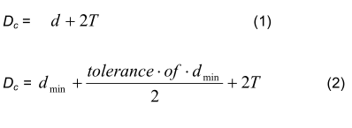
For tolerance see Tables 8, 9 and 10.
8.2 Chemical composition
8.2.1 Cast analysis
The cast analysis reported by the steel producer shall apply and conform to the requirements of Table 2.
NOTE:When welding tubes produced in accordance with this Part of this EN 10216, account should be taken of the fact that the behaviour of the steel during and after welding is dependent not only on the steel, but also on the applied heat treatment and the conditions of preparing for and carrying out the welding.
8.2.2 Product analysis
Option 3 : Product analysis for the tubes shall be supplied.
Table 3 specifies the permissible deviations of the product analysis from the specified limits on cast analysis given in Table 2.
Table 1 — Heat treatment conditions
| Steel grade | Heat treatment a |
Austenizing | Tempering | |||
| Steel name |
Steel number |
Temperature °C | Cooling Medium |
Temperature °C | Cooling medium |
|
| P195GH | 1.0348 | +N b | 880 to 940 | Air | - | - |
| P235GH | 1.0345 | +N b | 880 to 940 | Air | - | - |
| P265GH | 1.0425 | +N b | 880 to 940 | Air | - | - |
| 20MnNb6 | 1.0471 | +N b | 900 to 960 | Air | - | - |
| 16Mo3 | 1.5415 | +N b | 890 to 950 | Air | - | - |
| 8MoB5-4 | 1.5450 | +N b | 920 to 960 | Air | - | - |
| 14MoV6-3 | 1.7715 | +NT b c | 930 to 990 | Air | 680 to730 | air |
| 10CrMo5-5 | 1.7338 | +NT b c | 900 to 960 | Air | 650 to 750 | air |
| 13CrMo4-5 | 1.7335 | +NT b c | 900 to 960 | Air | 660 to 730 | air |
| 10CrMo9-10 | 1.7380 | +NT b c | 900 to 960 | Air | 680 to 750 | air |
| 11CrMo9-10 | 1.7383 | +QT | 900 to 960 | Air or Liquid | 680 to 750 | air |
| 25CrMo4 | 1.7218 | +QT | 860 to 900 | Air or Liquid | 620 to 680 | air |
| 20CrMoV13-5-5 | 1.7779 | +QT | 980 to 1030 | Air or Liquid | 680 to 730 | air |
| 15NiCuMoNb5-6-4 | 1.6368 | +NT c | 880 to 980 | Air | 580 to 680 | air |
| X11CrMo5+I | 1.7362+I | +I | 890 to 950 | Furnace Atmosphere |
- | - |
| X11CrMo5+NT1 | 1.7362+NT1 | +NT1 | 930 to 980 | Air | 730 to 770 | air |
| X11CrMo5+NT2 | 1.7362+NT2 | +NT2 c | 930 to 980 | air | 710 to 750 | air |
| X11CrMo9-1+I | 1.7386+I | +I | 950 to 980 | Furnace Atmosphere |
- | - |
| X11CrMo9-1+NT | 1.7386+NT | +NT c | 890 to 950 | air | 720 to 800 | air |
| X10CrMoVNb9-1 | 1.4903 | +NT c | 1040 to 1090 | air | 730 to 780 | air |
| X20CrMoV11-1 | 1.4922 | +NT c | 1020 to 1080 | air | 730 to 780 | air |
a +N = Normalising, +NT = Normalising + Tempering, +QT = Quenching + Tempering (air or liquid), +I = Isothermal Annealing.
b Normalising includes Normalising Forming.
c For these steel grades it may be necessary in the case of wall thickness T above 25 mm or T/D > 0,15 to apply quenching and tempering in order to achieve the intended structure and material properties . The decision shall be left to the discretion of the manufacturer but shall be stated to the customer at the time of enquiry and order. Steel tubes treated in such a way shall be designated by the steel name supplemented by the symbol “+QT “.
Table 2 — Chemical composition (cast analysis) a , in % by mass
| Steel grade | C | Si | Mn | P max |
S max |
Cr | Mo | Ni | Al tot | Cu | Nb | Ti max |
V | Cr+Cu +Mo+Ni |
Others | |
| Steel name | Steel number |
|||||||||||||||
| 195GH | 1.0348 | ≤ 0,13 | ≤ 0,35 | ≤ 0,70 | 0,025 | 0,020 | ≤ 0,30 | ≤ 0,08 | ≤ 0,30 | ≥ 0,020 b | ≤ 0,30 c | ≤ 0,010 d | 0,040 d |
≤ 0,02 d | ≤ 0,70 | - |
| P235GH | 1.0345 | ≤ 0,16 | ≤ 0,35 | ≤ 1,20 | 0,025 | 0,020 | ≤ 0,30 | ≤ 0,08 | ≤ 0,30 | ≥ 0,020 b | ≤ 0,30 c | ≤ 0,010 d | 0,040 d |
≤ 0,02 d | ≤ 0,70 | - |
| P265GH | 1.0425 | ≤ 0,20 | ≤ 0,40 | ≤ 1,40 | 0,025 | 0,020 | ≤ 0,30 | ≤ 0,08 | ≤ 0,30 | ≥ 0,020 b | ≤ 0,30 c | ≤ 0,010 d | 0,040 d |
≤ 0,02 d | ≤ 0,70 | - |
| 20MnNb6 | 1.0471 | ≤ 0,22 | 0,15 to 0,35 |
1,00 to 1,50 |
0,025 | 0,020 | - | - | - | ≤ 0,060 | ≤ 0,30 c | 0,015 to 0,10 |
- | - | - | - |
| 16Mo3 | 1.5415 | 0,12 to 0,20 e |
≤ 0,35 | 0,40 to 0,90 |
0,025 | 0,020 | ≤ 0,30 | 0,25 to 0,35 |
≤ 0,30 | ≤ 0,040 | ≤ 0,30 c | - | - | - | - | - |
| 8MoB5-4 | 1.5450 | 0,06 to 0,10 |
0,10 to 0,35 |
0,60 to 0,80 |
0,025 | 0,020 | ≤ 0,20 | 0,40 to 0,50 |
- | ≤ 0,060 | ≤ 0,30 c | - | 0,060 | - | - | B = 0,002 to 0,006 |
| 14MoV63 | 1.7715 | 0,10 to 0,15 |
0,10 to 0,35 |
0,40 to 0,70 |
0,025 | 0,020 | 0,30 to 0,60 |
0,50 to 0,70 |
≤ 0,30 | ≤ 0,040 | ≤ 0,30 c | - | - | 0,22 to 0,28 |
- | - |
| 10CrMo5-5 | 1.7338 | ≤ 0,15 | 0,50 to 1,00 |
0,30 to 0,60 |
0,025 | 0,020 | 1,00 to 1,50 |
0,45 to 0,65 |
≤ 0,30 | ≤ 0,040 | ≤ 0,30 c | - | - | - | - | - |
| 13CrMo4-5 | 1.7335 | 0,10 to 0,17 e |
≤ 0,35 | 0,40 to 0,70 |
0,025 | 0,020 | 0,70 to 1,15 |
0,40 to 0,60 |
≤ 0,30 | ≤ 0,040 | ≤ 0,30 c | - | - | - | - | - |
| 10CrM09-10 | 1.7380 | 0,08 to 0,14 |
≤ 0,50 | 0,30 to 0,70 |
0,025 | 0,020 | 2,00 to 2,50 |
0,90 to 1,10 |
≤ 0,30 | ≤ 0,040 | ≤ 0,30 c | - | - | - | - | - |
| 11CrMo9-10 | 1.7383 | 0,08 to 0,15 |
≤ 0,50 | 0,40 to 0,80 |
0,025 | 0,020 | 2,00 to 2,50 |
0,90 to 1,10 |
≤ 0,30 | ≤ 0,040 | ≤ 0,30 c | - | - | - | - | - |
| 25CrMo4 | 1.7218 | 0,22 to 0,29 |
≤ 0,40 | 0,60 to 0,90 |
0,025 | 0,020 | 0,90 to 1,20 |
0,15 to 0,30 |
≤ 0,30 | ≤ 0,040 | ≤ 0,30 c | - | - | - | - | - |
| 20CrMoV13-5-5 | 1.7779 | 0,17 to 0,23 |
0,15 to 0,35 |
0,30 to 0,50 |
0,025 | 0,020 | 3,00 to 3,30 |
0,50 to 0,60 |
≤ 0,30 | ≤ 0,040 | ≤ 0,30 c | - | - | 0,45 to 0,55 |
- | - |
| 15NiCuMoNb5-6-4 | 1.6368 | ≤ 0,17 | 0,25 to 0,50 |
0,80 to 1,20 |
0,025 | 0,020 | ≤ 0,30 | 0,25 to 0,50 |
1,00 to 1,30 |
≤ 0,050 | 0,50 to 0,80 |
0,015 to 0,045 |
- | - | - | - |
| X11CrMo5+I X11CrMo5+NT1 X11CrMo5+NT2 |
1.7362+I 1.7362+NT1 1.7362+NT2 |
0,08 to 0,15 |
0,15 to 0,50 |
0,30 to 0,60 |
0,025 | 0,020 | 4,00 to 6,00 |
0,45 to 0,65 |
- | ≤ 0,040 | ≤ 0,30 c |
- | - | - | - | - |
| X11CrMo9-1+I X11CrMo9-1+NT |
1.7386+I 1.7386+NT |
0,08 to 0,15 |
0,25 to 1,00 |
0,30 to 0,60 |
0,025 | 0,020 | 8,00 to 10,00 |
0,90 to 1.10 |
- | ≤ 0,040 | ≤ 0,30 c |
- | - | - | -- | |
| X10CrMoVNb9-1 | 1.4903 | 0,08 to 0,12 |
0,20 to 0,50 |
0,30 to 0,60 |
0,025 | 0,020 | 8,00 to 9,50 |
0,85 to 1,05 |
≤ 0,40 | ≤ 0,040 | ≤ 0,30 c |
0,06 to 0,10 |
- | 0,18 to 0,25 |
- | N = 0,030 to 0,070 |
| X20CrMoV11-1 | 1.4922 | 0,17 to 0,23 f |
0,15 to 0,50 |
≤ 1,00 | 0,025 | 0,020 | 10,00 to 12,50 |
0,80 to 1,20 |
0,30 to 0,80 |
≤ 0,040 | ≤ 0,30 c |
- | - | 0,25 to 0.35 |
- | - |
a Elements not included in this Table shall not be intentionally added to the steel without the agreement of the purchaser, except for elements which may be added for finishing the cast. All appropriate measures shall be taken to prevent the addition of undesirable elements from scrap or other materials used in the steel making process.
b This requirement is not applicable provided the steel contains a sufficient amount of other nitrogen binding elements which shall be reported. When using titanium, the producer shall verify that (Al+Ti/2)≥0,020%
c Option 2: In order to facilitate subsequent forming operations, an agreed maximum copper content lower than indicated and an agreed specified maximum tin content shall apply
d The content of these elements need not to be reported unless intentionally added to the cast.
e For wall thickness ≥ 30 mm the carbon content may be increased by 0,02 % for cast and product analysis.
f The upper carbon value of 0,23 % shall not be exceeded for product analysis.
Table 3 — Permissible deviations of the product analysis from specified limits on cast analysis given in Table 2
| Element | Limiting value for the cast analysis in accordance with Table 2 % by mass | Permissible deviation of the product analysis % by mass |
| C | ≤ 0,29 | ± 0,02 |
| Si | ≤ 0,40 | ± 0,05 |
| > 0,40 to ≤ 1,00 | ± 0,06 | |
| Mn | ≤ 1,00 | ± 0,05 |
| > 1,00 to ≤ 1,50 | ± 0,10 | |
| P | ≤ 0,025 | + 0,005 |
| S | ≤ 0,010 | + 0,003 |
| > 0,010 ≤ 0,020 | + 0,005 | |
| Al | ≤ 0,060 | ± 0,005 |
| B | ≤ 0,006 | ± 0,001 |
| Cr | ≤ 1,00 | ± 0,05 |
| > 1,00 to ≤ 10,00 | ± 0,10 | |
| > 10,00 to ≤ 12,50 | ± 0,15 | |
| Cu | ≤ 0,80 | ± 0,05 |
| Mo | ≤ 0,35 | ± 0,03 |
| > 0,35 to ≤ 1,20 | ± 0,04 | |
| N | ≤ 0,070 | ± 0,01 |
| Nb | ≤ 0,10 | ± 0,005 |
| Ni | ≤ 0,35 | ± 0,05 |
| > 0,35 to ≤ 1,30 | ± 0,07 | |
| Ti | ≤ 0,060 | + 0,010 |
| V | ≤ 0,10 | + 0,01 |
| > 0,10 to ≤ 0,55 | ± 0,03 |
8.3 Mechanical properties
8.3.1 Mechanical properties at and below room temperature
The mechanical properties at and below room temperature of the tubes shall conform to the requirements in Table 4 and in clauses 11.3, 11.4, 11.5 and 11.6.
8.3.2 Proof strength at elevated temperature
The minimum proof strength R p0,2 values at elevated temperature are given in Table 5.
Option 6: Proof strength R p0,2 shall be verified. The test temperature shall be specified at the time of enquiry and order.
Table 4 — Mechanical properties
| Steel grade | Upper yield strength or proof strength R eH or Rp 0,2 for Wall Thickness T min. |
Tensile Strength Rm |
Elongation A min. % a |
Minimum average absorbed energy KV J at a temperature of °C |
|||||||||
| Steel name | Steel number |
T ≤ 16 | 16 < T ≤ 40 | 40 < T ≤ 60 | 60 < T ≤ 100 | l | t | l | t | ||||
| MPa * | MPa * | MPa * | MPa * | MPa * | 20 | 0 | -10 | 20 | 0 | ||||
| P195GH | 1.0348 | 195 | - | - | - | 320 to 440 | 27 | 25 | - | 40 c | 28 d | - | 27 c |
| P235GH | 1.0345 | 235 | 225 | 215 | - | 360 to 500 | 25 | 23 | - | 40 c | 28 d | - | 27 c |
| P265GH | 1.0425 | 265 | 255 | 245 | - | 410 to 570 | 23 | 21 | - | 40 c | 28 d | - | 27 c |
| 20MnNb6 | 1.0471 | 355 | 345 | 335 | - | 500 to 650 | 22 | 20 | - | 40 c | - | - | 27 c |
| 16Mo3 | 1.5415 | 280 | 270 | 260 | - | 450 to 600 | 22 | 20 | 40 c | - | - | 27 c | - |
| 8MoB5-4 | 1.5450 | 400 | - | - | - | 540 to 690 | 19 | 17 | 40 c | - | - | 27 c | - |
| 14MoV6-3 | 1.7715 | 320 | 320 | 310 | - | 460 to 610 | 20 | 18 | 40 c f | - | - | 27 c | - |
| 10CrMo5-5 | 1.7338 | 275 | 275 | 265 | - | 410 to 560 | 22 | 20 | 40 c | 27 c | |||
| 13CrMo4-5 | 1.7335 | 290 | 290 | 280 | - | 440 to 590 | 22 | 20 | 40 c | 27 c | |||
| 10CrMo9-10 | 1.7380 | 280 | 280 | 270 | - | 480 to 630 | 22 | 20 | 40 c | - | - | 27 c | - |
| 11CrMo9-10 | 1.7383 | 355 | 355 | 355 | - | 540 to 680 | 20 | 18 | 40 c | - | - | 27 c | - |
| 25CrMo4 | 1.7218 | 345 | 345 | 345 | - | 540 to 690 | 18 | 15 | 40 c f | - | - | 27 c | - |
| 20CrMoV13-5-5 | 1.7779 | 590 | 590 | 590 | - | 740 to 880 | 16 | 14 | 40 c f | 27 c | - | ||
| 15NiCuMoNb5-6-4 | 1.6368 | 440 | 440 | 440 | 440 e |
610 to 780 | 19 | 17 | 40 c f | - | - | 27 c | - |
| X11CrMo5+I | 1.7362+I | 175 | 175 | 175 | 175 | 430 to 580 | 22 | 20 | 40 c | - | - | 27 c | - |
| X11CrMo5+NT1 | 1.7362+NT1 | 280 | 280 | 280 | 280 | 480 to 640 | 20 | 18 | 40 c | - | - | 27 c | - |
| X11CrMo5+NT2 | 1.7362+NT2 | 390 | 390 | 390 | 390 | 570 to 740 | 18 | 16 | 40 c | - | - | 27 c | - |
| X11CrMo9-1+I | 1.7386+I | 210 | 210 | 210 | - | 460 to 640 | 20 | 18 | 40 c | - | - | 27 c | - |
| X11CrMo9-1+NT | 1.7386+NT | 390 | 390 | 390 | - | 590 to 740 | 18 | 16 | 40 c | - | - | 27 c | - |
| X10CrMoVNb9-1 | 1.4903 | 450 | 450 | 450 | 450 | 630 to 830 | 19 | 17 | 40 c f | 27 c | |||
| X20CrMoV11-1 | 1.4922 | 490 | 490 | 490 | 490 | 690 to 840 | 17 | 14 | 40 c f | 27 c | |||
a l = longitudinal t = transverse
b To be verified when options 4 and/or 5 are/is specified, unless footnote f) applies.
c Option 4: Impact energy shall be verified.
d Option 5: Longitudinal impact energy shall be verified.
e For wall thickness 60 mm< T ≤ 80 mm.
f Impact test mandatory for wall thickness T ≥ 16 mm.
* MPa = 1 N/mm 2
Table 5 — Minimum proof strength R p0,2 at elevated temperature
| Steel grade | Wall thickness mm |
Minimum proof strength R p0,2 MPa a at temperature of °C |
|||||||||||
| Steel name | Steel number | 100 | 150 | 200 | 250 | 300 | 350 | 400 | 450 | 500 | 550 | 600 | |
| P195GH | 1.0348 | ≤16 | 175 | 165 | 150 | 130 | 113 | 102 | 94 | - | - | - | - |
| P235GH | 1.0345 | ≤ 60 | 198 | 187 | 170 | 150 | 132 | 120 | 112 | 108 | - | - | - |
| P265GH | 1.0425 | ≤ 60 | 226 | 213 | 192 | 171 | 154 | 141 | 134 | 128 | - | - | - |
| 20MnNb6 | 1.0471 | ≤ 60 | 312 | 292 | 264 | 241 | 219 | 200 | 186 | 174 | - | - | - |
| 16Mo3 | 1.5415 | ≤ 60 | 243 | 237 | 224 | 205 | 173 | 159 | 156 | 150 | 146 | - | - |
| 8MoB5-4 | 1.5450 | ≤ 16 | 368 | 368 | 368 | 368 | 368 | 368 | 368 | - | - | - | - |
| 14MoV6-3 | 1.7715 | ≤ 60 | 282 | 276 | 267 | 241 | 225 | 216 | 209 | 203 | 200 | 146 | - |
| 10CrMo5-5 | 1.7338 | ≤ 60 | 240 | 228 | 219 | 208 | 165 | 156 | 148 | 144 | 143 | - | - |
| 13CrMo4-5 | 1.7335 | ≤ 60 | 264 | 253 | 245 | 236 | 192 | 182 | 174 | 168 | 166 | - | - |
| 10CrMo9-10 | 1.7380 | ≤ 60 | 249 | 241 | 234 | 224 | 219 | 212 | 207 | 193 | 180 | - | - |
| 11CrMo9-10 | 1.7383 | ≤ 60 | 323 | 312 | 304 | 296 | 289 | 280 | 275 | 257 | 239 | - | - |
| 25CrMo4 | 1.7218 | ≤ 60 | - | 315 | 305 | 295 | 285 | 265 | 225 | 185 | |||
| 20CrMoV13-5-5 | 1.7779 | ≤ 60 | - | 575 | 570 | 560 | 550 | 510 | 470 | 420 | 370 | - | - |
| 15NiCuMoNb5-6-4 | 1.6368 | ≤ 80 | 422 | 412 | 402 | 392 | 382 | 373 | 343 | 304 | - | - | - |
| X11CrMo5+I | 1.7362+1 | ≤ 100 | 156 | 150 | 148 | 147 | 145 | 142 | 137 | 129 | 116 | - | - |
| X11CrMo5+NT1 | 1.7362+NT1 | ≤ 100 | 245 | 237 | 230 | 223 | 216 | 206 | 196 | 181 | 167 | - | - |
| X11CrMo5+NT2 | 1.7362+NT2 | ≤ 100 | 366 | 350 | 334 | 332 | 309 | 299 | 289 | 280 | 265 | - | - |
| X11CrMo9-1+I | 1.7386+I | ≤ 60 | 187 | 186 | 178 | 177 | 175 | 171 | 164 | 153 | 142 | 120 | - |
| X11CrMo9-1+NT | 1.7386+NT | ≤ 60 | 363 | 348 | 334 | 330 | 326 | 322 | 316 | 311 | 290 | 235 | - |
| X10CrMoVNb9-1 | 1.4903 | ≤ 100 | 410 | 395 | 380 | 370 | 360 | 350 | 340 | 320 | 300 | 270 | 215 |
| X20CrMoV11-1 | 1.4922 | ≤ 100 | - | - | 430 | 415 | 390 | 380 | 360 | 330 | 290 | 250 | - |
a 1 MPa = 1 N/mm 2
8.4 Appearance and internal soundness
8.4.1 Appearance
8.4.1.1 The tubes shall be free from external and internal surface defects that can be detected by visual examination.
8.4.1.2 The internal and external surface finish of the tubes shall be typical of the manufacturing process and, where applicable, the heat treatment employed. Normally the finish and surface condition shall be such that any surface imperfections requiring dressing can be identified.
8.4.1.3 It shall be permissible to dress, only by grinding or machining, surface imperfections provided that,after doing so, the wall thickness in the dressed area is not less than the specified minimum wall thickness. All dressed areas shall blend smoothly into the contour of the tube.
8.4.1.4 Any surface imperfection, which is demonstrated to be deeper than 5 % of the wall thickness T or 3 mm whichever is the smaller, shall be dressed.
This requirement does not apply to surface imperfection with a depth equal or less 0,3 mm
8.4.1.5 Surface imperfections which encroach on the specified minimum wall thickness shall be considered defects and tubes containing these shall be deemed not to conform to this Part of EN 10216.
8.4.2 Internal soundness
8.4.2.1 Leak Tightness
The tubes shall pass a hydrostatic test (see 11.8.1) or electromagnetic test (see 11.8.2) for leak-tightness.
Unless option 7 is specified, the choice of the test method is at the discretion of the manufacturer.
Option 7: The test method for verification of leak-tightness in accordance with 11.8.1 or 11.8.2 is specified by the purchaser.
8.4.2.2 Non-Destructive Testing
The tubes of test category 2 shall be subjected to a non-destructive testing for the detection of longitudinal imperfections, in accordance with11.11.1.
Option 8: The tubes of test category 2 shall subjected to a non-destructive testing for the detection of transverse imperfections in accordance with11.11.2.
Option 9: The tubes of test category 2 shall be subjected to a non-destructive testing for the detection of the laminar imperfections in accordance with11.11.3.
8.5 Straightness
The deviation from straightness of any tube length L shall not exceed 0,0015 L. Deviations from straightness over any one metre length shall not exceed 3 mm.
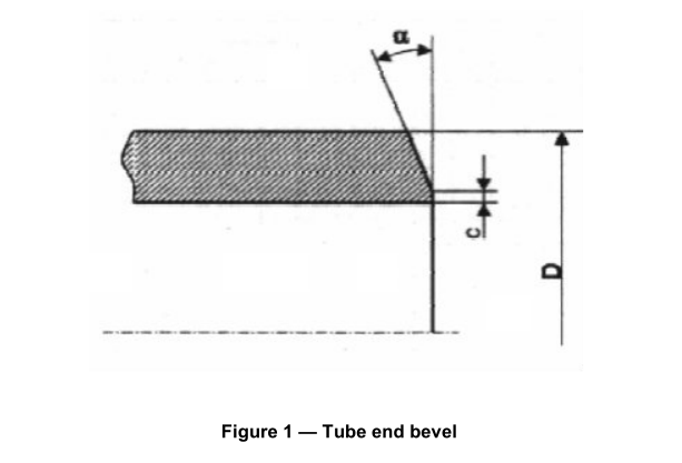
8.6 Preparation of ends
Tubes shall be delivered with square cut ends. The ends shall be free from excessive burrs.
Option10: The tubes shall be delivered with bevelled ends (see figure 1). The bevel shall have an angle α of 30°(+5° ,-0° )with a root face C of 1,6 mm ± 0,8 mm, except that for wall thickness T greater than 20 mm, an agreed alternative bevel may be specified
8.7 Dimensions, masses and tolerances
8.7.1 Diameter and wall thickness
Unless option 11 is specified, tubes shall be delivered by outside diameter D and wall thickness T.
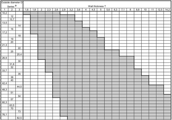
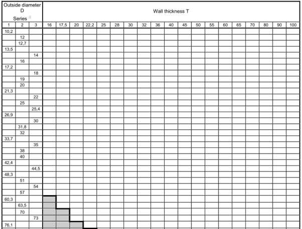
Preferred outside diameters D and wall thicknesses T have been selected from ENV 10220 and are given in Table 6.
NOTE Dimensions which are different from those in Table 6 may be agreed.
Option 11: The tubes shall be delivered in accordance withone of the following sets of dimensions as specified at the time of enquiry and order:
outside diameter D and minimum wall thickness T min ;
inside diameter d and wall thickness T for d ≥ 220 mm;
inside diameter d and minimum wall thickness T min for d ≥ 220 mm;
minimum inside diameter d min and wall thickness T for d min ≥ 220 mm;
minimum inside diameter d min and minimum wall thickness T min for d min ≥220 mm.
Table 6 — Preferred dimensions
dimensions in mm
8.7.2 Mass
For the mass per unit length the provisions of ENV 10220 apply except that for the steel grade X11CrMo9-1+I,X11CrMo9-1+NT, X10CrMoVNb9-1 and X20CrMoV11-1 a density of 7,77 kg/dm 3 shall be used.
8.7.3 Lengths
Unless option 12 is specified, the tubes shall be delivered in random length. The delivery length range shall be agreed at the time of enquiry and order.
Option 12: The tubes shall be delivered in exact lengths and the length shall be specified at the time of enquiry and order. For the tolerances see 8.7.4.2.
8.7.4 Tolerances
8.7.4.1 Tolerances on diameter and thickness
The diameter and the wall thickness of the tubes shall be within the relevant tolerance limits given in Tables 7, 8, 9, 10 or 11.
Out of roundness is included in the tolerances on diameter and eccentricity is included in the tolerances on wall thickness.
Table 7 — Tolerances on outside diameter and wall thicknes
| Outside Diameter D mm | Tolerances on D |
Tolerances on T for a T/D ratio | |||
| ≤ 0,025 | > 0,025 ≤ 0,050 |
> 0,050 ≤ 0,10 |
> 0,10 | ||
| D ≤ 219,1 | ± 1% or ± 0.5mm whichever is the greater |
± 12,5% or ± 0.4mm whichever is the greater | |||
| D > 219,1 | ± 20% | ± 15% | ± 12,5% | ± 10% a | |
a For outside diameters D ≥ 355,6 mm it is permitted to exceed the upper wall thickness locally by a further 5% of the wall thickness T
Table 8 — Tolerances on inside diameter and wall thickness
| Tolerances on inside diameter | Tolerances on T for a T/d ratio | |||||
| d | d min | ≤ 0,03 | > 0,03 ≤ 0,06 |
> 0,06 ≤ 0,12 |
> 0,12 | |
| ± 1% or ± 2 mm whichever is the greater | (+ 2% ,0)or (+ 4 mm,0) |
whichever is the greater | ± 20% | ± 15% | ± 12,5% | ± 10% a |
a For outside diameters D ≥ 355,6 mm it is permitted to exceed the upper wall thickness locally by a further 5% of the wall thickness T
Table 9 — Tolerances on outside diameter and minimum wall thickness
| Outside diameter D mm | Tolerances on D | Tolerances on T min for a T min /D ratio | |||
| ≤ 0,02 | > 0,02 ≤ 0,04 |
> 0,04 ≤ 0,09 |
> 0,09 | ||
| D ≤ 219,1 | ± 1% or ± 0.5mm whichever is the greater |
(+ 28%,0) or (+ 0.8 mm,0) whichever is the greater | |||
| D > 219,1 | + 50% 0 |
+ 35% 0 |
+ 28% 0 |
+ 22% a 0 |
|
a For outside diameters D ≥ 355,6 mm it is permitted to exceed the upper wall thickness locally by a further 5% of the wall thickness T
Table 10 — Tolerances on inside diameter and minimum wall thickness
| Tolerances on inside diameter |
Tolerances on T min for a T min /d ratio |
|||
| d | d min | ≤ 0,05 | > 0,05 ≤ 0,1 |
> 0,1 |
| ± 1% or ± 2 mm whichever is the greater |
(+2%,0) or (+ 4 mm,0) whichever is the greater | + 35% 0 |
+ 28% 0 |
+ 22% a 0 |
a For outside diameters D ≥ 355,6 mm it is permitted to exceed the upper wall thickness locally by a further 5% of the wall thickness T
Table 11 — Tolerances on outside diameter and wall thickness for tube ordered cold finished
| Tolerance on D | Tolerance on T |
| ± 0,5% or ± 0,3 mm whichever is the greater |
± 10% or ± 0,2 mm whichever is the greater |
8.7.4.2 Tolerances on exact lengths
The tolerances for exact lengths shall be as given in Table 12.
Table 12 — Tolerances on exact lengths
Dimension in mm
| Length L | Tolerance on exact length |
| L ≤ 6000 | +10 0 |
| 6000 < L ≤ 12 000 | +15 0 |
| L > 12 000 | + by agreement 0 |
9.1 Types of inspection
Conformity to the requirements of the order, for tubes in accordance with this Part of EN 10216, shall be checked by specific inspection.
When an inspection document 3.1.B is specified the material manufacturer shall state in the confirmation of the order whether he is operating according to a “quality-assurance system”, certified by a competent Body established within the Community and having undergone a specific assessment for materials.
NOTE See the Directive 97/23/EC Annex I section 4.3 third paragraph.
9.2 Inspection documents
9.2.1 Types of inspection documents
Unless option 13 is specified, an inspection certificate 3.1.B, in accordance with EN 10204, shall be issued.
Option 13: One of the inspection documents 3.1.A, 3.1.C or 3.2 in accordance with EN 10204 shall be issued.
If an inspection document 3.1.A, 3.1.C or 3.2 is specified, the purchaser shall notify the manufacturer of the name and address of the organisation or person who is to carry out the inspection and produce the inspection document. In the case of the inspection report 3.2 it shall be agreed which party shall issue the certificate.
NOTE:Document 3.1.A is not acceptable for compliance with the Directive 97/23/EC.
9.2.2 Content of inspection documents
The content of the inspection document shall be in accordance with prEN 10168.
In all types of inspection documents a statement on the conformity of the products delivered with the requirements of this specification and the order shall be included.
The inspection certificate or inspection report shall contain the following codes and information:
A commercial transactions and parties involved;
B description of products to which the inspection document applies;
C02-C03 direction of the test pieces and testing temperature;
C10-C13 tensile test;
C40-C43 impact test if applicable;
C60-C69 other tests;
C71-C92 chemical composition on cast analysis (product analysis if applicable);
D01 marking and identification, surface appearance, shape and dimensional properties;
D02-D99 leak-tightness test; NDT, material identification if applicable;
Z validation.
In addition for inspection document 3.1.B the manufacturer shall state the references to the certificate (see 9.1) of the appropriate “quality-assurance system”, if applicable.
9.3 Summary of inspection and testing
Non-alloy steel tubes shall be inspected and tested in accordance with test category 1 or test category 2 as specified at the time of inquiry and order (see 6.1).
Alloy steel tubes shall be inspected and tested in accordance with test category 2 (see Table 13).
Inspection and testing to be carried out are summarised in Table 13.
Table 13 — Summary of inspection and testing
| Type of inspection and test | Frequency of Testing |
Refer to | Test category (TC) |
||
| 1 | 2 | ||||
| Mandatory tests |
Cast analysis | One per cast | 8.2.1 - 11.1 | X | X |
| Tensile test at room temperature | One per sample tube |
8.3.1 - 11.2.1 | X | X | |
| Flattening test for D < 600 mm and T/D ratio ≤ 0,15 but T ≤ 40 mm or a Ring tensile test for D > 150 mm and T ≤ 40 mm |
8.3 - 11.3 -11.4 | X | X | ||
| Drift expanding test for D ≤ 150 mm and T ≤ 10 mm or a b Ring expanding test for D ≤ 114.3 mm and T ≤ 12,5 mm |
8.3 - 11.5 - 11.6 | X | X | ||
| Impact test at 20° C for Group A c | 8.3 - 11.7 | X | X | ||
| Leak tightness test | Each tube | 8.4.2.1 - 11.8 | X | X | |
| Dimensional inspection | 8.7.1 - 11.9 | X | X | ||
| Visual examination | 11.10 | X | X | ||
| NDT for the detection of longitudinal imperfections | Each tube | 8.4.2.2 - 11.11.1 | - | X | |
| Material identification of alloy steels | 11.12 | X | X | ||
| Optional tests |
Product analysis (Option 3) | One per cast | 8.2.2 - 11.1 | X | X |
| Tensile test at elevated temperature (Option 6) | One per cast and same heat treatment condition |
8.3.2 - 11.2.2 | X | X | |
| Impact test for Group B c (Option 4) | One per sample tube | 8.3 - 11.7 | X | X | |
| Longitudinal impact test at-10°C for non-alloy steel grades (Option 5) | 8.3 - 11.7 | X | X | ||
| Wall thickness measurement away from tube ends (Option 15) | 8.7.1 - 11.9 | X | X | ||
| NDT for the detection of transverse imperfections (Option 8) | Each tube | 8.4.2.2 - 11.11.2 | - | X | |
| NDT for the detection of laminar imperfections (Option 9) | 8.4.2.2 - 11.11.3 | - | X | ||
a The choice of flattening or ring tensile test and of drift expanding test or ring expanding test is at the manufacturer’s discretion.
b For steel grades X10CrMoVNb9-1 and X20CrMoV11-1 tubes, the flattening or ring tensile test and the drift expanding test or ring expanding test shall be carried out at one end of 20 % of the tubes of each test unit.
c Group A: tubes having wall thickness T ≥ 16 mm manufactured from steel grades 14MoV6-3, 25CrMo4, 20CrMoV13-5-5, 15NiCuMoNb5-6-4, X10CrMoVNb9-1 and X20CrMoV11-1 Group B: All tubes except group A.
10.1 Frequency of tests
10.1.1 Test unit
For normalised formed tubes a test unit shall comprise tubes of the same specified diameter and wall thickness,the same steel grade, the same cast, the same manufacturing process.
For tubes which are furnace heat treated a test unit shall comprise tubes of the same specified diameter and wall thickness, the same steel grade, the same cast, the same manufacturing process, subjected to the same finishing treatment in a continuous furnace or heat treated in the same furnace charge in a batch-type furnace.
The number of tubes per test unit shall conform to Table 14.
Table 14 — Number of tubes per test unit
| Outside diameter D mm |
Maximum number of tubes per test unit |
| D ≤ 114,3 | 200 |
| 114,3 < D ≤ 323,9 | 100 |
| D > 323,9 | 50 |
10.1.2 Number of sample tubes per test unit
The following number of sample tubes shall be selected from each test unit :
test category 1: one sample tube;
test category 2: two sample tubes; when the total number of tubes is less than 20, only one sample tube
10.2 Preparation of samples and test pieces
10.2.1 Selection and preparation of samples for product analysis
Samples for product analysis shall be taken from the test pieces or samples for mechanical testing or from the whole thickness of the tube at the same location as the mechanical test samples, in accordance with ISO 14284.
10.2.2 Location, orientation and preparation of samples and test pieces for mechanical test
10.2.2.1 General
Samples and test pieces shall be taken at the tube ends and in accordance with the requirements of EN ISO 377.
10.2.2.2 Test pieces for tensile tests
The test pieces for the tensile tests at room temperature shall be prepared in accordance with EN 10002-1.
The test piece for the tensile tests at elevated temperature shall be prepared in accordance with EN 10002-5.
At the manufacturer's discretion:
for tubes with an outside diameter D ≤ 219,1 mm the test piece shall be either a full tube section or a strip section and shall be taken in a direction longitudinal to the axis of the tube;
for tubes with an outside diameter D > 219,1 mm the test piece shall either a machined test piece with circular cross section from an unflattened sample or a strip section and be taken in a direction either
longitudinal or transverse to the axis of the tube.
10.2.2.3 Test pieces for flattening test, ring tensile test, drift expanding test and ring expanding test
The test pieces for the flattening test, ring tensile test, drift expanding test and the ring expanding test shall consist of a full tube section in accordance with EN 10233, EN 10237, EN 10234 or EN 10236 respectively.
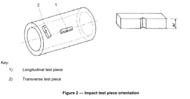
10.2.2.4 Test pieces for impact test
Three standard Charpy V-notch test pieces shall be prepared in accordance with EN 10045-1. If the wall thickness is such that standard test pieces cannot be produced without flattening of the section, then test pieces of width less than 10 mm, but not less than 5 mm shall be prepared; the largest obtainable width shall be used.
Where test pieces of least 5 mm width cannot be obtained, the tubes shall not be subjected to impact testing.
Unless otherwise specified (see Option 5), the test pieces shall be taken transverse to the tube axis unless D min ,as calculated by the following equation, is greater than the specified outside diameter, in which case longitudinal test pieces shall be used:
D min = (T-5) + [ 756,25 / (T-5) ] (5)
The test pieces shall be prepared such that the axis of the notch is perpendicular to the surface of the tube, see Figure 2.
11.1 Chemical analysis
The elements to be determined and reported shall be those specified in Table 2. The choice of a suitable physical or chemical analytical method for the analysis shall be at the discretion of the manufacturer. In case of dispute the method used shall be agreed between manufacturer and purchaser taking into account CR 10261.
11.2 Tensile test
11.2.1 Tensile test at room temperature
The test shall be carried out at room temperature in accordance with EN 10002-1, and the following determined:
the tensile strength (R m );
the upper yield strength (R eH ) or if a yield phenomenon is not present the 0,2 % proof strength (R p0,2 );
the percentage elongation after fracture with a reference to a gauge length ( L 0 ) of So ⋅ 65 , 5 ; if a non-proportional test piece is used, the percentage elongation value shall be converted to the value for a gauge length So Lo ⋅ = 65 , 5 using the conversion Tables in EN ISO 2566-1.
11.2.2 Tensile test at elevated temperature
The test shall be carried out in accordance with EN 10002-5 at the temperature agreed at the time of enquiry and order (see 6.2) and the proof strength (R p0,2 ) shall be determined.
11.3 Flattening test
The test shall be carried out in accordance with EN 10233.
The tube section shall be flattened in a press until the distance H between the platens reaches the value given by the following equation:

where :
H is the distance between platens, in mm, to be measured under load;
D is the specified outside diameter, in mm;
T is the specified wall thickness, in mm;
C is the constant factor of deformation (given in Table 15).
Table 15 — Flattening test - Constant factor of deformation C
| Steel grade | Data | |
| Steel name | Steel number | C |
| P195GH | 1.0348 | 0,09 |
| P235GH | 1.0345 | 0,09 |
| P265GH | 1.0425 | 0,07 |
| 20MnNb6 | 1.0471 | 0,07 |
| 16Mo3 | 1.5415 | 0,07 |
| 8MoB5-4 | 1.5450 | 0,05 |
| 14MoV63 | 1.7715 | 0,05 |
| 10CrMo5-5 | 1.7338 | 0,08 |
| 13CrMo4-5 | 1.7335 | 0,07 |
| 10CrMo9-10 | 1.7380 | 0,07 |
| 11CrMo9-10 | 1.7383 | 0,07 |
| 25CrMo4 | 1.7218 | 0,06 |
| 20CrMoV13-5-5 | 1.7779 | 0,05 |
| 15NiCuMoNb5-6-4 | 1.6368 | 0,05 |
| X11CrMo5+I | 1.7362+I | 0,05 |
| X11CrMo5+NT1 | 1.7362+NT1 | 0,05 |
| X11CrMo5+NT2 | 1.7362+NT2 | 0,05 |
| X11CrMo9-1+I | 1.7386+I | 0,05 |
| X11CrMo9-1+NT | 1.7386+NT | 0,05 |
| X10CrMoVNb9-1 | 1.4903 | 0,05 |
| X20CrMoV11-1 | 1.4922 | 0,05 |
After testing, the test piece shall be free from cracks or breaks. However, slight incipient cracks at its edges shall not be regarded as justification for rejection.
11.4 Ring tensile test
The test shall be carried out in accordance with EN 10237.
The tube section shall be subjected to strain in the circumferential direction until fracture occurs.
After fracture the test pieces shall not show any visible cracks without the use of magnifying aids (excluding the fracture point).
11.5 Drift expanding test
The test shall be carried out in accordance with EN 10234.
The tube section shall be expanded with a 60° conical tool until the percentage increase in outside diameter shown in Table 16 is reached.
Table 16 — Drift expanding test requirements
| Steel grade | % increase in outside diameter for d/D a | |||
| Steel name | Steel number | ≤ 0,6 | > 0,6 ≤ 0,8 | > 0,8 |
| P195GH | 1.0348 | 12 | 15 | 19 |
| P235GH | 1.0345 | 10 | 12 | 17 |
| P265GH | 1.0425 | 8 | 10 | 15 |
| 20MnNb6 | 1.0471 | 8 | 10 | 15 |
| 16Mo3 | 1.5415 | 8 | 10 | 15 |
| 8MoB5-4 | 1.5450 | 8 | 10 | 15 |
| 14MoV63 | 1.7715 | 8 | 10 | 15 |
| 10CrMo5-5 | 1.7338 | 8 | 10 | 15 |
| 13CrMo4-50 | 1.7335 | 8 | 10 | 15 |
| 10CrMo9-10 | 1.7380 | 8 | 10 | 15 |
| 11CrMo9-10 | 1.7383 | 8 | 10 | 15 |
| 25CrMo4 | 1.7218 | 6 | 8 | 12 |
| 20CrMoV13-5-5 | 1.7779 | 6 | 8 | 12 |
| 15NiCuMoNb5-6-4 | 1.6368 | 8 | 10 | 15 |
| X11CrMo5+I | 1.7362+I | 8 | 10 | 15 |
| X11CrMo5+NT1 | 1.7362+NT1 | 8 | 10 | 15 |
| X11CrMo5+NT2 | 1.7362+NT2 | 8 | 10 | 15 |
| X11CrMo9-1+I | 1.7386+I | 8 | 10 | 15 |
| X11CrMo9-1+NT | 1.7386+NT | 8 | 10 | 15 |
| X10CrMoVNb9-1 | 1.4903 | 8 | 10 | 15 |
| X20CrMoV11-1 | 1.4922 | 6 | 8 | 12 |
| a d = D - 2T | ||||
After testing, the test piece shall be free from cracks or breaks. However, slight incipient cracks at its edges shall not be regarded as justification for rejection.
11.6 Ring expanding test
The test shall be carried out in accordance with EN 10236.
The tube section shall be expanded with a conical tool until it breaks. The surface outside the fracture zone shall be free from cracks or breaks. However, slight incipient cracks at its edges shall not be regarded as justification for rejection.
11.7 Impact test
11.7.1 The test shall be carried out in accordance with EN 10045-1 at the temperature given in Table 4.
11.7.2 The mean value of the three test pieces shall meet the requirements given in Table 4. One individual value may be below the specified value, provided that it is not less than 70 % of that value.
11.7.3 If the width (W) of the test piece is less than 10 mm, the measured impact energy (KV p ) shall be converted to the calculated impact energy(KV c ) using the following equation:
where:
KV c is the calculated impact energy, in J;
KV p is the measured impact energy, in J;
W is the width of the test piece, in mm.
The calculated impact energy KV c shall conform to the requirements given in 11.7.2.
11.7.4 If the requirements of 11.7.2 are not met, then an additional set of three test pieces may be taken at the discretion of the manufacturer from the same sample and tested. To consider the test unit as conforming, after testing the second set, the following conditions shall be satisfied simultaneously:
the average value of the six tests shall be equal to or greater than the specified minimum average value;
not more than two of the six individual values may be lower than the specified minimum average value;
not more than one of the six individual values may be lower than 70 % of the specified minimum average value.
11.7.5 The dimensions in millimetres of the test pieces, the measured impact energy values and the resulting average value shall be reported.
11.8 Leak tightness test
11.8.1 Hydrostatic test
The hydrostatic test shall be carried out at a test pressure of 70 bar
2) or at a test pressure P calculated using the following equation, whichever is lower:
where :
P is the test pressure, in bar;
D is the specified outside diameter, in mm;
T is the specified wall thickness, in mm;
S is the stress, in
MPa, corresponding to 70 % of the specified minimum yield strength (see Table 4) for the steel grade concerned.
The test pressure shall be held for not less than 5 s for tubes with an outside diameter D less than or equal to 457 mm and for not less than 10 s for tubes with an outside diameter D greater than 457 mm.
The tube shall withstand the test without showing leakage or visible deformation.
2) 1 bar = 100 kPa
NOTE:This hydrostatic leak-tightness test is not a strength test.
Option 14: A test pressure different from that specified in 11.8.1 and corresponding to stresses below 90% of the specified minimum yield strength (see Table 4) for the steel grade concerned is specified.
11.8.2 Electromagnetic test
The test shall be carried out in accordance with EN 10246-1.
11.9 Dimensional inspection
Specified dimensions, including straightness, shall be verified.
The outside diameter shall be measured at tube ends. For tubes with outside diameter D ≥ 406,4 mm, the diameter may be measured using a circumference tape.
Unless option 15 is specified the wall thickness shall be measured at both tube ends.
Option 15: The wall thickness shall be measured away from the tube ends in accordance withan agreed procedure.
11.10 Visual examination
Tubes shall be visually examined to ensure conformity to the requirements of 8.4.1.
11.11 Non-destructive testing
11.11.1 Tubes of test category 2 shall be subjected to a Non-Destructive Testing for the detection of longitudinal imperfections, in accordance with EN 10246-7, to acceptance level U2, sub-category C or EN 10246-5 acceptance level F2.
Unless option 16 is specified, the selection of the test method is at the discretion of the manufacturer.
Option 16: The test method is specified by the purchaser.
Regions at the tube ends not automatically tested shall either be subjected to manual/semi-automatic ultrasonic testing in accordance with EN 10246-7 to acceptance level U2, sub-category C or be cropped off.
11.11.2 If option 8 is specified (see 8.4.2.2), the tubes shall be subjected to ultrasonic testing for the detection of transverse imperfections in accordance with EN 10246-6 to acceptance level U2, sub-category C.
11.11.3 If option 9 is specified (see 8.4.2.2), the tubes shall be subjected to ultrasonic testing for the detection of the laminar imperfections in accordance with EN 10246-14 to acceptance level U2.
11.11.4 For tubes ordered by minimum wall thickness T min (see option 11), the acceptance level shall apply to the calculated wall thickness T c as determined in accordance with the formula stated in clause 8.1.
11.12 Material identification
Each tube made from alloy steel (see 5.1) shall be tested by an appropriate method to ensure that the correct grade is being supplied.
11.13 Retests, sorting and reprocessing
For retest, sorting and reprocessing the requirements of EN 10021 shall apply.
12.1 Marking to be applied
The marking shall be indelibly marked on each tube at least at one end. For tubes with outside diameter D ≤ 51 mm the marking on tubes may be replaced by the marking on a label attached to the bundle or box.
The marking shall include the following information:
the manufacturer's name or trade mark ;
the number of this European standard and the steel name (see 5.2);
the test category in case of non-alloy steel grades;
the cast number or a code number;
the mark of the inspection representative;
an identification number (e.g. order or item number) which permits the correlation of the product or delivery unit to the related document.
Example of marking:
X - EN 10216-2 - P265GH - TC1 - Y- Z 1 - Z 2
where:
X is the manufacturer's mark;
TC1 is the designation of the test category 1;
Y is the cast number or a code number;
Z 1 is the mark of the inspection representative;
Z 2 is the identification number.
12.2 Additional marking
Option 17: Additional marking, as agreed upon at the time of enquiry and order, shall be applied.
The tubes shall be delivered without a temporary protective coating.
Option 18: A temporary protective coating or durable coating and/or lining shall be applied.

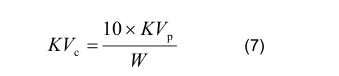
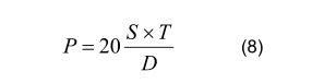
Ceramic lined pipe is made through self-propagating high-temperature synthesis (SHS) technique.
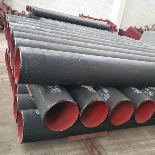
Cast basalt lined steel pipe is composed by lined with cast basalt pipe, outside steel pipe and cement mortar filling between the two layers.
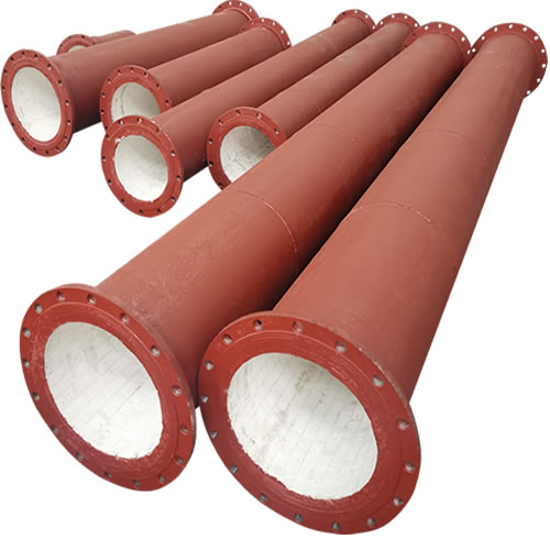
Ceramic tile lined pipes have very uniform coating of specially formulated ceramic material that is affixed to the inner of the pipe.
The material of the rare earth alloy wear-resistant pipe is ZG40CrMnMoNiSiRe, which is also the grade of rare earth alloy steel.
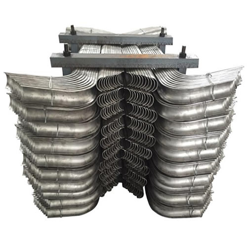
Tubes Erosion Shields are used to protect boiler tubing from the highly erosive effects of high temperatures and pressures thereby greatly extending tube life.
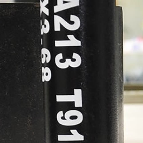
The ASTM A213 T91 seamless tubes are primarily used for boiler, superheater, and heat-exchanger.

When you partner with Sunny Steel, you can stop worrying about meeting deadlines thanks to our responsive and timely service. You'll also say goodbye to unnecessary shopping around. Instead, you'll get white glove service from an expert who understands your needs and can get you the materials you need quickly.