Blind Flanges
A blind flange (also called a 'closure plate flange') is installed at the end of a piping system to terminate a pipe.
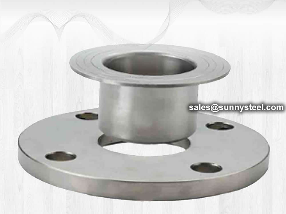
Lap joint flanges are a type of flange assembly commonly used in low-pressure systems or applications where frequent disassembly may be required.
They consist of two main components: a lap joint stub end and a lap joint flange.
Download PDFLap joint flange is used with a lap joint stub end fitting. Lap joint flange is similar to a slip-on flange, but with two differences. The radius and the flat face, both allow the flange to secure against the stub end fitting. This is useful where alignment of bolt holes is difficult, such as with spools to be attached to flanged nozzles of vessels. A lap joint is used in low pressure applications and not suitable where high external of heavy loads are present.
These flanges are always used with either a stub end or taft which is butt welded to the pipe with the flange loose behind it. This means the stub end or taft always makes the face. The lap joint is favoured in low pressure applications because it is easily assembled and aligned. To reduce cost these flanges can be supplied without a hub and/or in treated, coated carbon steel.
Lap joint flanges are usually used in low pressure applications and are not suitable when there are high loads on the flange pair. Some types of piping require the use of lap joint flanges. For example, metallic pipe that has been plastic lining may have lap joint flanges.
Using lap joint flanges might be an option for saving costs when the piping is made of exotic materials. By using a lap joint flange, the wetted materials would consist of the exotic materials and the flange would be carbon steel. Since the flange doesn’t ever come in contact with the process fluid, it would not be affected by the fluids.
Dimensions on the lap joint flange are similar to weld neck, slip on or socket weld flanges. The backing flange has the same number of bolt holes, size and thickness of a weld neck or slip on flange.
Lap joint flange (simplified as LTF flange) shape is similar to slip on flange, it has a curved radius at the bore, which can connect with a stub end fittings and slide over the pipe. In this form, the pipe is usually welded to this stub end so the lap joint flange can rotate freely around the stub end.
The advantage of this combination that it will be easy with alignment for the bolt hole, easy to install and uninstall, much more convenient to do examinations and maintenance.
The lap joint stub end is butt welded to the pipe, while the lap joint flange is slid onto the pipe before the final welding takes place. The flange has a raised flat portion called the lap, which allows it to overlap with the flanged portion of the stub end, creating a tight seal.
Lap joint flanges are known for their ease of installation and cost-effectiveness. They provide flexibility and can accommodate slight misalignment or movement between the pipe and the flange. However, they are not as strong as other types of flanges, such as welding neck or slip-on flanges.
It's important to note that lap joint flanges should not be used in applications with high temperatures or high pressures, as they may not provide the necessary strength and sealing capabilities. Consulting with a qualified engineer or referring to relevant standards and guidelines is recommended when selecting the appropriate flange type for a specific application.
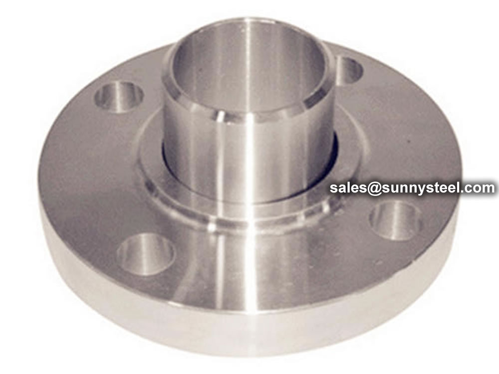
Lap joint flange with stub end
Lap joint flange is typically used for low pressure application. It is not suitable when the flange pair need to bear high loads. Some pipes required to use this type flange, like a metal pipe already lined with plastic may have to use lap joint flanges.

A lap joint flange consists of two main components:
Flat Face Flange: The flat face flange is the main body of the lap joint flange. It has a flat surface with bolt holes to secure the flange to the mating flange or pipe.
Stub End: The stub end is a short piece of pipe with a lap joint configuration. It slides over the pipe end and allows the flange to rotate freely, providing flexibility during alignment.
The lap joint flange is typically used with a gasket to ensure a leak-proof joint between the flanges.
One of the primary advantages of lap joint flanges is their easy assembly and disassembly. This feature simplifies installation, maintenance, and repair tasks, reducing downtime and overall costs.
The lap joint design of the flange allows for angular misalignment of pipes, ensuring a tight and leak-proof joint even when pipes are not perfectly aligned.
Lap joint flanges provide a cost-effective solution for piping systems that require frequent disassembly. The reusability of these flanges reduces replacement costs.
Lap joint flanges are often made from corrosion-resistant materials, such as stainless steel or carbon steel with corrosion-resistant coatings, ensuring long-term reliability in corrosive environments.
Lap joint flanges play a crucial role in various industries, offering a practical and cost-effective solution for pipe connections that require easy assembly and disassembly. Their design allows for flexibility during alignment, making them suitable for a wide range of applications in the petrochemical, oil and gas, water treatment, food and beverage, and chemical processing industries. When it comes to ensuring efficient and reliable pipe connections, lap joint flanges prove to be an essential component in modern piping systems.
A stub end is always used with a lap joint flange as a backing flange. There are three different types of stub ends, type A, B and C.
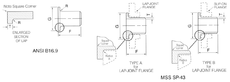
Stub end include long or short pattern length. The end of long pattern is also known as ASA Stub Ends. The short end is used with the larger flanges of ANSI 300 and 600. They are commonly used in most sizes ANSI 900 and above.
Slip on flange is essentially a ring placed over the pipe end. And the flange face extending a sufficient distance from the pipe end, so as to apply a weld on the inner diameter. The outer diameter of slip on flange can also be welded to the rear side of flange. Comparing to weld neck flange, slip on flange has lower material cost and easier to align.
The lap flange is very similar to a slip on flange. From the outside, it almost looks like the same. But you look on the backside, the holes and faces of lap joint flange has a curved radius to accommodate the lap joint stub end.
If type B or type C stub end is used, the slip on flange can be used as the lap joint flange.
The datasheets we have on this site are shown below. For simplicity sake, only datasheets that adhere to B16.5 are shown. ASME B16.5 covers flange dimensions from ½” to 24”. For sizes larger than this (ASME B16.47 Series A & B), please visit our flange datasheets page.
| Class | Flat Face |
|---|---|
| ANSI 150 | Lap Joint, ANSI Class 150 (in) |
| ANSI 300 | Lap Joint, ANSI Class 300 (in) |
| ANSI 400 | Lap Joint, ANSI Class 400 (in) |
| ANSI 600 | Lap Joint, ANSI Class 600 (in) |
| ANSI 900 | Lap Joint, ANSI Class 900 (in) |
| ANSI 1500 | Lap Joint, ANSI Class 1500 (in) |
| ANSI 2500 | Lap Joint, ANSI Class 2500 (in) |
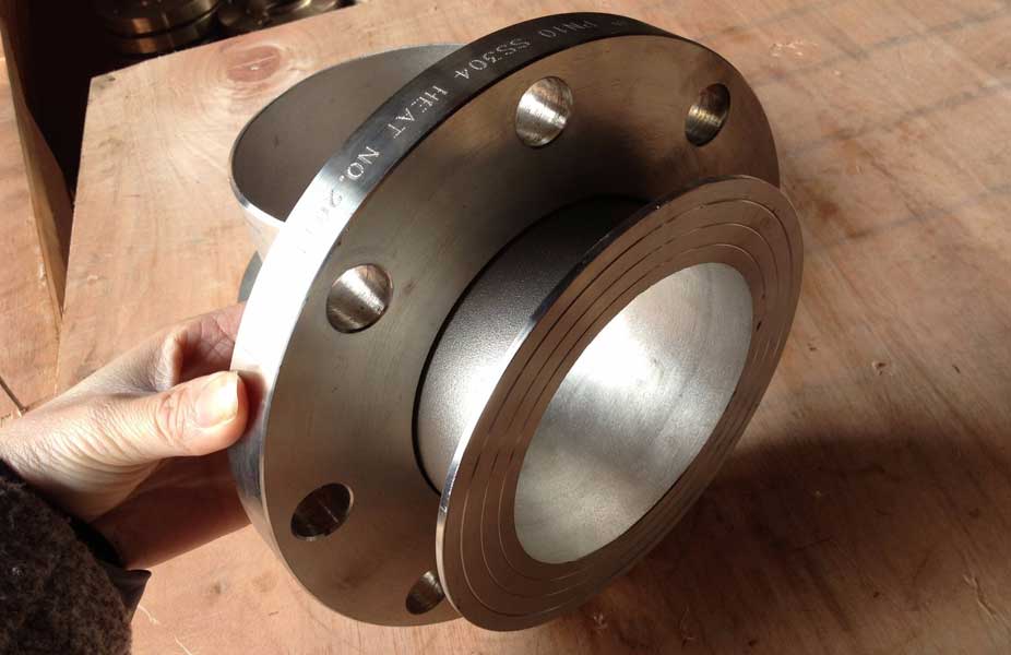
Lap joint flange with stub end
By using lap joint flanges, work can be simplified in situations that require frequent and rapid disassemble and assembly during the operation of a plant. The ability to spin that backing flange compensates for misalignment of the bolt holes during assembly.
Lap joint flanges are extremely similar to slip-on flanges, with the primary difference being that the bore and face have a curved radius to accommodate a lap joint stub-end. Lap joint flanges and stub-end assemblies are commonly employed in circumstances where regular disassembly for inspection is necessary.
To a lap joint flange, only the stub end is touch with the pipe and fluid, the backing flange no need to touch it . It means you could only replace the stub end , no need to replace the backing flange, so the lap joint flange can decrease the cost of the piping systems.
A Stub end Flange or more commonly called Lap Joint Flanges are used with Stub Ends. A Stub End adapter slides thru the Flange and is welded to the pipe. The Lap Joint Flange is similar to the Slip On Flange except it is flat across the face and has a radius machined at the bore.

Pipe flanges are manufactured in all the different materials like stainless steel, cast iron, aluminium, brass, bronze, plastic etc. but the most used material is forged carbon steel and have machined surfaces.
Flanges are welded to pipe and equipment nozzle. Accordingly, it is manufactured from the following materials;
The list of materials used in manufacturing is covered in ASME B16.5 & B16.47.
Commonly used Forged material grads are
| Material | Fittings | Flanges | Valves | Bolts & Nuts |
|---|---|---|---|---|
| Carbon Steel | A234 Gr WPA | A105 | A216 Gr WCB | A193 Gr B7 A194 Gr 2H |
| A234 Gr WPB | A105 | A216 Gr WCB | ||
| A234 Gr WPC | A105 | A216 Gr WCB | ||
| Carbon Steel Alloy High-Temp |
A234 Gr WP1 | A182 Gr F1 | A217 Gr WC1 | A193 Gr B7 A194 Gr 2H |
| A234 Gr WP11 | A182 Gr F11 | A217 Gr WC6 | ||
| A234 Gr WP12 | A182 Gr F12 | A217 Gr WC6 | ||
| A234 Gr WP22 | A182 Gr F22 | A217 Gr WC9 | ||
| A234 Gr WP5 | A182 Gr F5 | A217 Gr C5 | ||
| A234 Gr WP9 | A182 Gr F9 | A217 Gr C12 | ||
| Carbon Steel Alloy Low-Temp |
A420 Gr WPL6 | A350 Gr LF2 | A352 Gr LCB | A320 Gr L7 A194 Gr 7 |
| A420 Gr WPL3 | A350 Gr LF3 | A352 Gr LC3 | ||
| Austenitic Stainless Steel | A403 Gr WP304 | A182 Gr F304 | A182 Gr F304 | A193 Gr B8 A194 Gr 8 |
| A403 Gr WP316 | A182 Gr F316 | A182 Gr F316 | ||
| A403 Gr WP321 | A182 Gr F321 | A182 Gr F321 | ||
| A403 Gr WP347 | A182 Gr F347 | A182 Gr F347 |
ASTM standards define the specific manufacturing process of the material and determine the exact chemical composition of pipes, fittings and flanges, through percentages of the permitted quantities of carbon, magnesium, nickel, etc., and are indicated by "Grade".
The usual materials of flanges include stainless steel, carbon steel, aluminum and plastic. The choice of the material largely depends on the purpose of the flange. For example, stainless steel is more durable and is necessary for heavy use. On the other hand, plastic is more feasible for use in the home because of its reasonable price and easy installation. The materials used for flanges are under the designation of the American Society of Mechanical Engineers.
The most common materials for pipe flanges (forged grades) are: ASTM A105 (carbon steel high temperature to match A53/A106/API 5L pipes), A350 Grades LF1/2/3 (carbon steel low temperature to match A333 pipes), A694 Grades F42 to F80 (high yield carbon steel to match API 5L pipe grades), ASTM A182 Grades F5 to F91 (alloy steel flanges to match A335 pipes), A182 Grade F304/316 (stainless steel flanges to match A312 SS pipes), A182 Gr. F44/F51/F53/F55 (duplex and super duplex to match A790/A928 pipes) and various nickel alloy grades (Inconel, Incoloy, Hastelloy, Monel).
The material qualities for these flanges are defined in the ASTM standards.
For example, a carbon steel pipe can be identified with Grade A or B, a stainless-steel pipe with Grade TP304 or Grade TP321, a carbon steel fitting with Grade WPB etc.
Pipe Flange Standards mainly include three systems in the world, ANSI/ASME flange system(American), DIN flange system(European system), JIS flange system, other system made according to this three systems, like GB flange standard, which mainly made according to ANSI/ASME and DIN flange standard, Duwa Piping supplies those flanges with top quality and soonest delivery time.
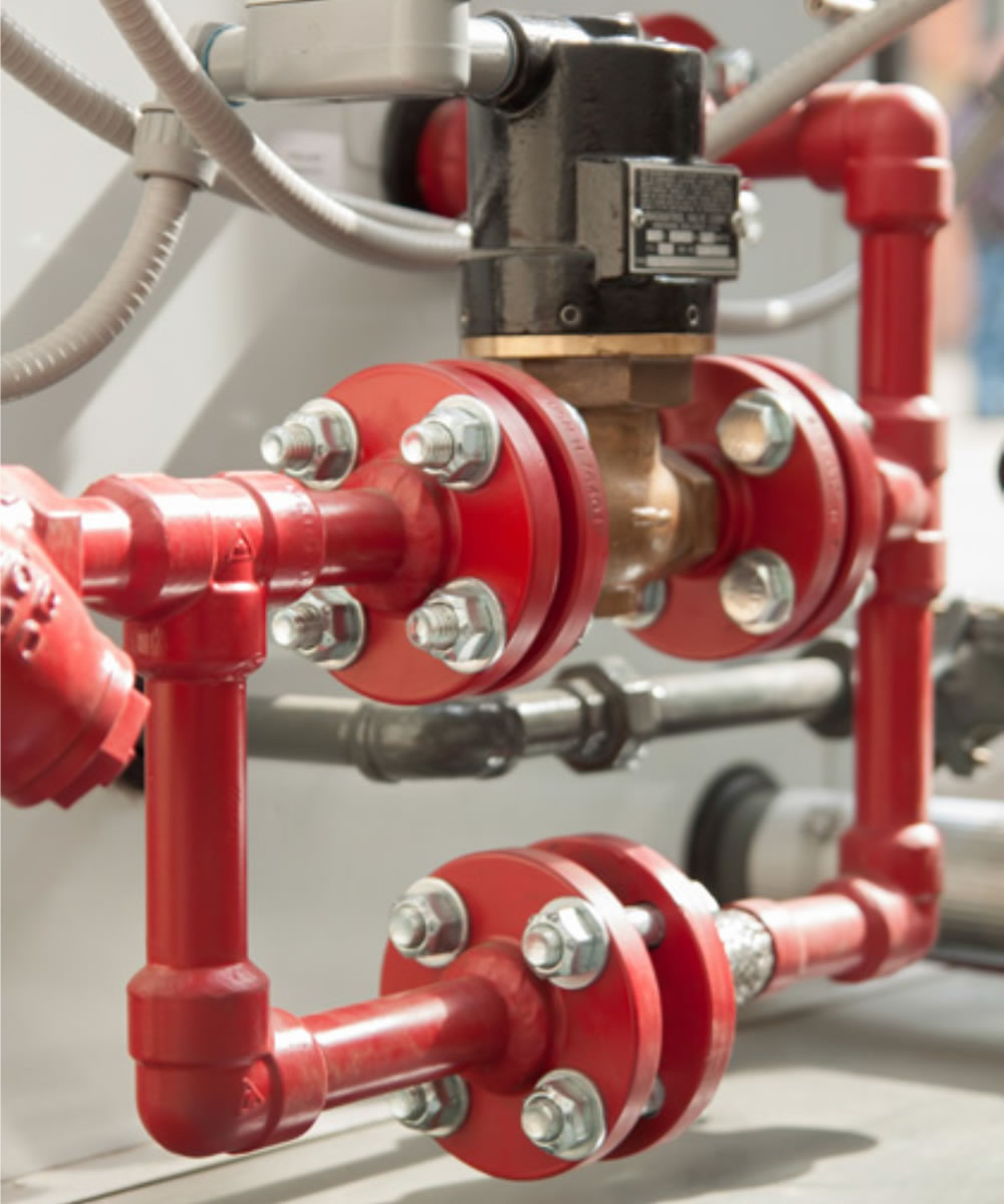
A flange is a method of connecting pipes, valves, pumps, and other equipment to form a piping system. It also provides easy access for cleaning, inspection, or modification.
When a piping joint requires to be dismantled, flanges are being used. These are primarily used on equipment, valves, and specialty items. Breakout flanges are provided at predetermined intervals in certain pipelines where maintenance is a regular occurrence. The flanges, gaskets, and bolting make up a flanged joint, which is made up of three separate but interconnected components. To achieve a leak-proof joint, special controls are required in the selection and application of all of these elements.
Here are the details of Flanges about their advantages and their applications.
Pipes, valves, pumps, and other parts are connected with flanges to form a piping system. Generally, flanges are welded or screwed together. The use of flanges makes pipe system maintenance and repair a breeze. Instead of taking the entire pipe for inspection, a small section of the pipe can be carefully investigated to use a flange to locate the fault.
The following are the five most important benefits of The following are the five most important benefits of flanges:
A flange is a method of connecting pipes, valves, pumps, and other equipment to form a piping system. It also provides easy access for cleaning, inspection, or modification. Flanges are usually welded or screwed.
In many applications, engineers need to find a way to close off a chamber or cylinder in a very secure fashion, usually because the substance inside must differ from the substance outside in composition or pressure.
They do this by fastening two pieces of metal or other material together with a circle of bolts on a lip. This “lip” is a flange.
You can connect two sections of metal piping by soldering or welding them together, but pipes connected in this way are very susceptible to bursting at high pressures. A way of connecting two sections of pipe more securely is by having flanged ends that you can connect with bolts. This way, even if gases or liquids build up to high pressures inside the pipe, it will often hold with no problem.
In order to connect two sections of a large, enclosed area, it is often best to used flanges and bolts. An example of this is the connection between the engine and the transmission in an automobile. In this case, both the engine and the transmission contain a number of moving parts that can easily get damaged if they get dust or other small objects inside of them. By connecting the outer casings of the engine and transmission in this way, engineers protect the inner workings of both.
Flanges have a specific purpose in cameras and other electronic devices. Though flanges in such items do not usually have to sustain high pressures, they do have to hold tight so they can keep out harmful particles. These flanges are usually found connecting two different materials, such as the glass of a lens and the rest of the body of the camera.
The most frequently asked questions regarding flanges and flange fittings have to do with how flanges fit on specific steel tube and steel pipe ends.
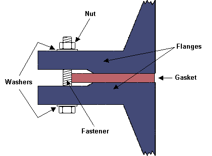
Flanges have flat or flush surfaces that are vertical to the pipe to which they are attached. The attachment process involves mechanically joining two or more faces using bolts, adhesives, collars, or welds. Due to the attachment requirements, a flange must fit the equipment or pipe that it’s designed. That’s why it’s necessary to check all the possible specifications and dimensions to ascertain that it’s of the right size, type, and material.
Pipe flanges, gaskets, and bolts are the three parts that comprise a flanged connection. Gaskets and bolts are typically made of the same flange materials or a material approved for the pipe components. Each component comes in various materials that suit specific applications and must be matched correctly for proper functioning. The gaskets come in two conventional types: full-face gaskets and ring gaskets. Full-face gaskets have the bolt holes visible and pair up with raised-face gaskets. Ring gaskets tend to be smaller rings minus the bolt holes and pair up with flat-faced flanges. Securing the flange components requires matching the surfaces evenly and plumb, adjusting as needed for a uniform fit. Once all surfaces match, bring the flanges together and secure at least two of the bolts. Refine the alignment, so the remaining bolt holes match and their corresponding bolts are tightly secured.
Properly sizing a flange for pipe use depends not only on the type of flange but its compatible piping. The pipe must slip into the flange’s inside diameter easily and securely, and the outside diameter should cover wall holes. Once you determine the specific flange type and material you need for the job, you’ll need to take several measurements. The four measurements you’ll need are the inside diameter, outside diameter, bolt hole count, and bolt hole center. You’ll need to align each of these measurements from opposing bolt holes to get the most accurate readings. Take all measurements from edge to edge and try to get as precise as possible to match the correct product. Round up bolt diameter to the next half or whole step since bolts measure half or whole inches. Once you have all four measurements, check them against the manufacturer’s table to find the correct flange. Most manufacturers list these specifications on their websites for easy reference.
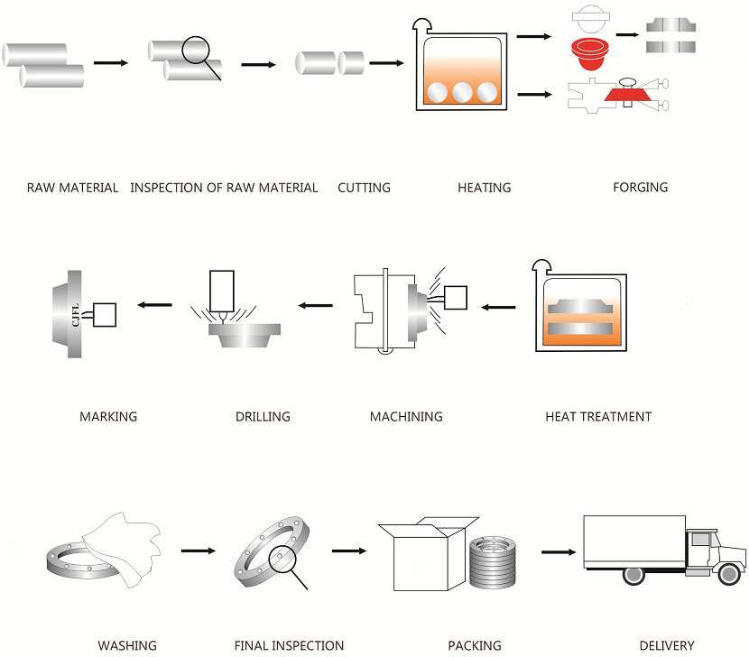
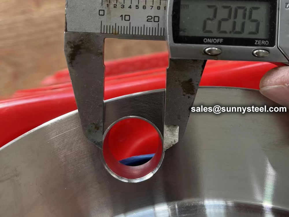
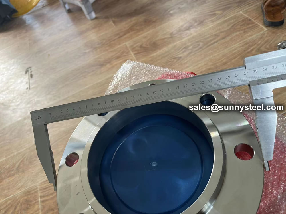
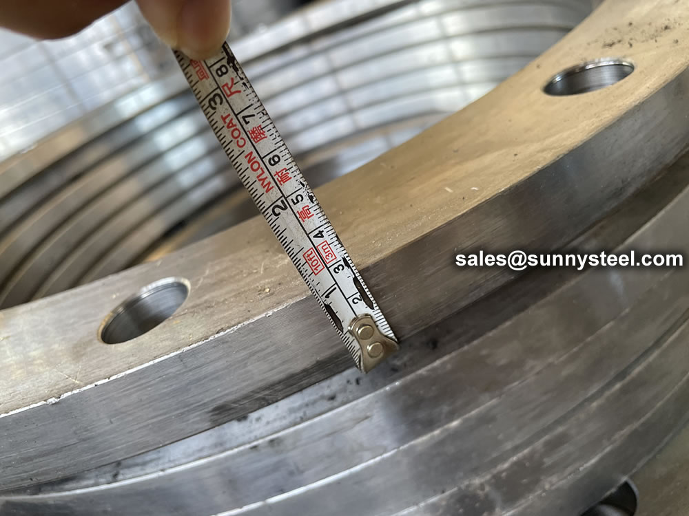
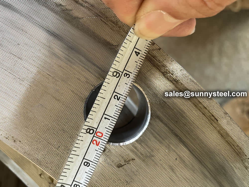
Before dispatching from manufacture each flange is inspected to ensure quality. During an inspection you have to check the following;
ASME B16.5 and B16.47 standards cover permissible tolerances for inspection.
Flanges are used to connect pipes or other equipment components in various industries, and they come in a variety of materials and sizes. Flange material standards are developed by standard-setting organizations and describe the properties and characteristics of different materials that can be used to make flanges. Some examples of commonly used flange material standards include:
The choice of flange material standard will depend on various factors such as the application, the environment, the fluid being transported, and the required performance characteristics. For example, high-pressure applications may require flanges made from materials with high strength and durability, while corrosive environments may require flanges made from materials with good resistance to corrosion.
There are many ways to connect flanges, including threading, welding or bolting. The threaded flange is best for low pressure or smaller pipelines because it can maintain its seal. When your pipeline is larger or high pressure, then the welded flange is preferable. A boiler room is one place where welded blind flanges might be used, due to the high pressure involved.
Flanged joints: flanges, bolts and nuts and gaskets
A flange is a external rib at the end of pipes, valves and other flow devices to assemble them.
Dimensions of the flanges are up to specific Standards : DIN, ANSI, AS, BS, JIS
A flanged connection requires two flanges (the “main” and the “companion”), a set of bolts and nuts (whose number depends on the flange diameter and class) and two sealing gaskets. Flanged connections have to be executed and supervised by trained personnel, as the quality of the joint has a critical impact on the performance of the piping system / pipeline (the standard TSE – TS EN 1591 Part 1-4, “Flanges and their joints”, defines a number of requirements for the execution of proper flanged connections). Whereas all elements of the joint are critical, experience shows most leaks are originated by the improper installation of the sealing elements, i.e. the gaskets.
The typical pipe to flange connections are welded or threaded. Welded flanges are used for pipelines and piping systems with high pressures and temperatures, and with diameters above 2 inches.
Threaded connections are instead used for installations of smaller diameter and not subject to severe mechanical forces such as expansion, vibration, contraction, oscillation (forces that would crack the threaded joint). In all these critical cases, butt weld connections are recommended.
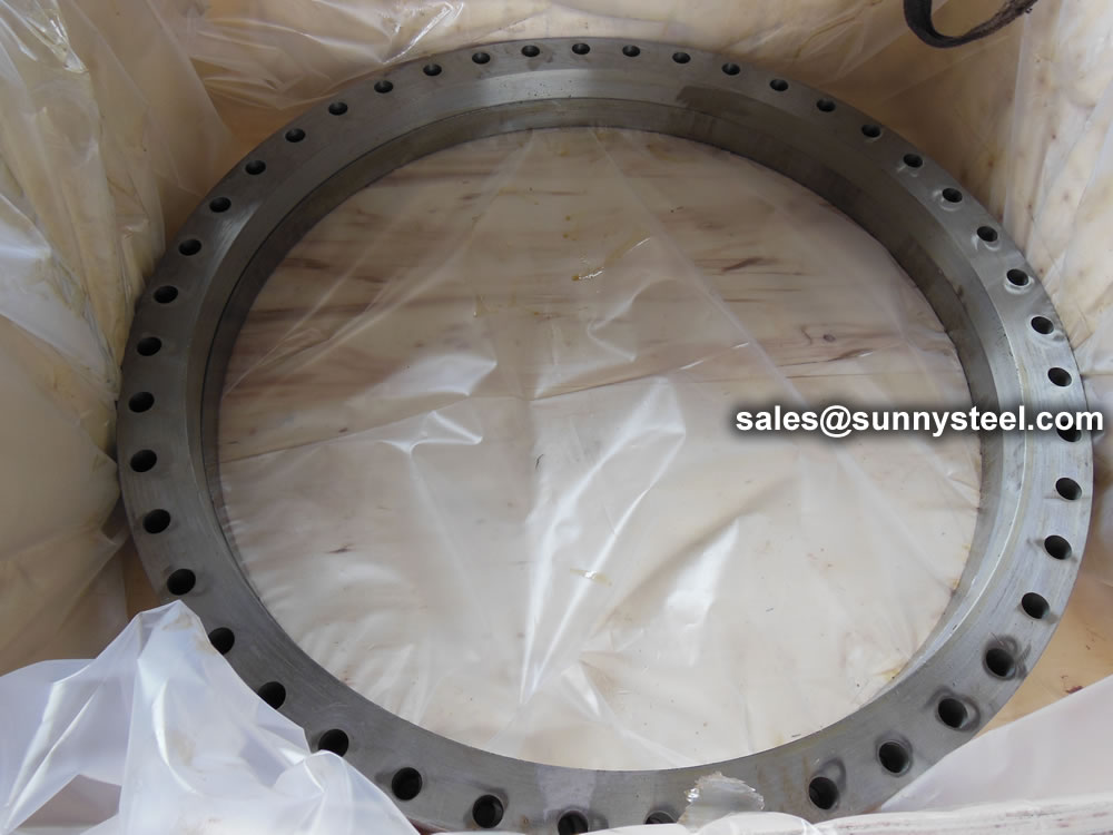
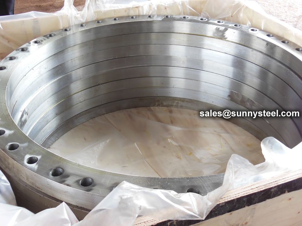
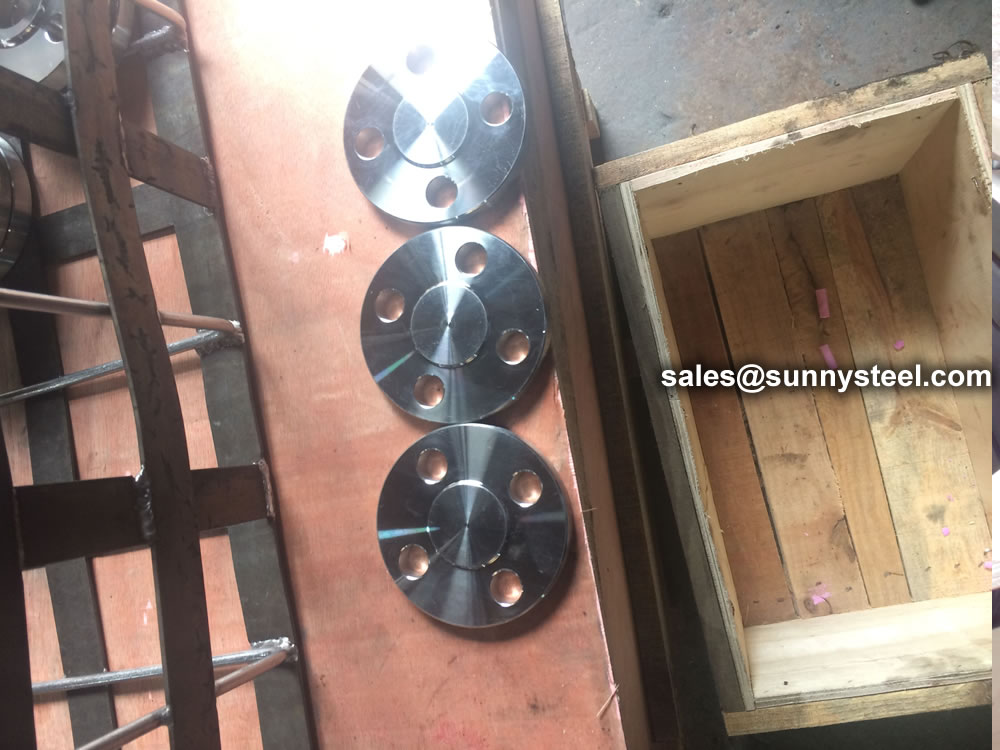
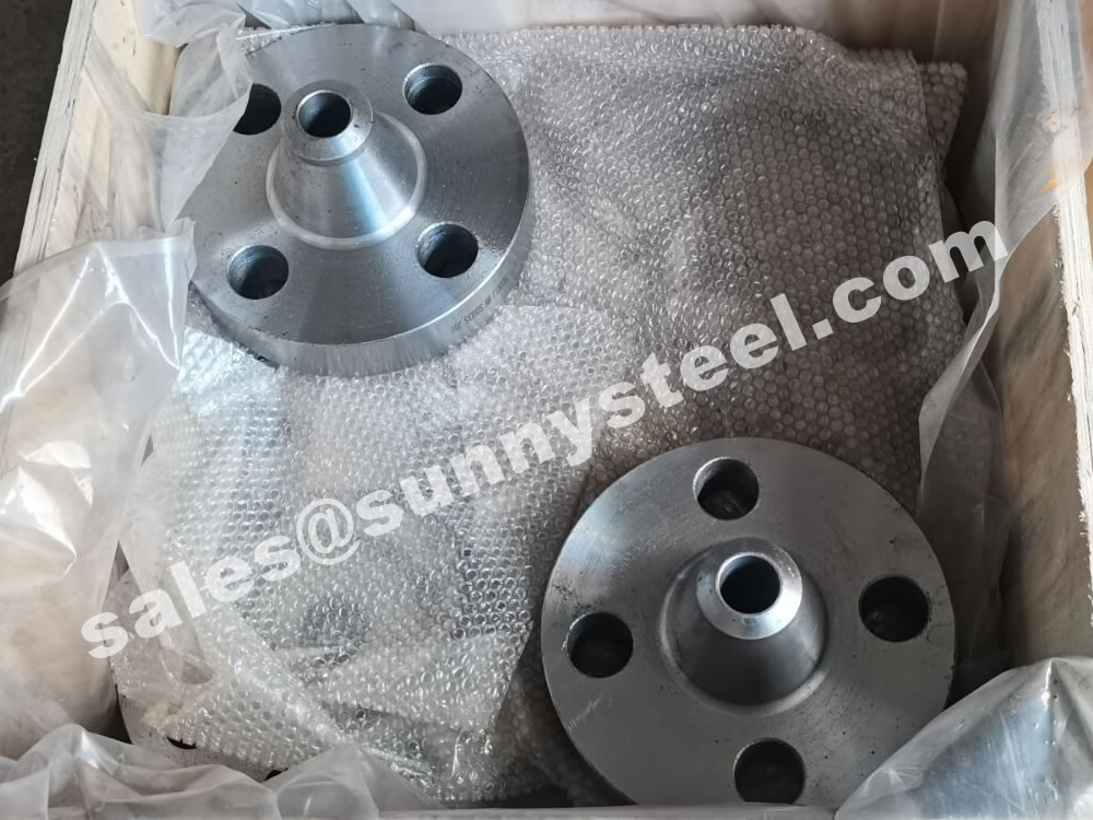
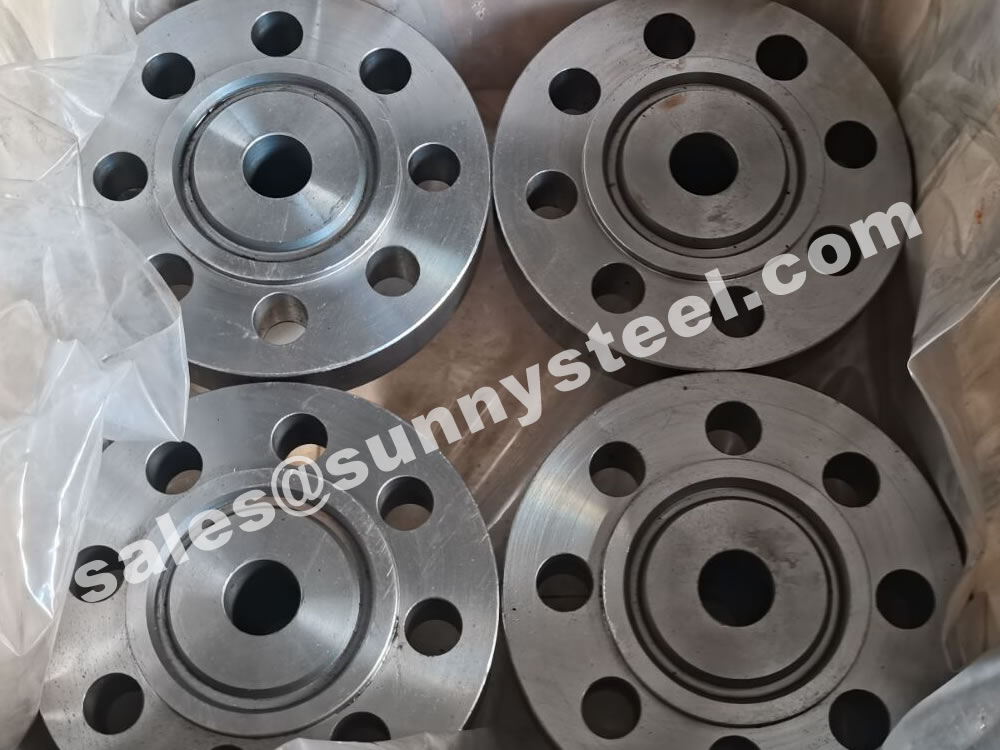
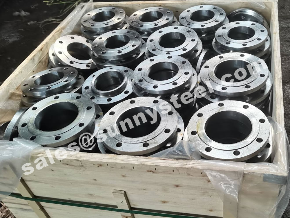
Steel flanges must be packed with seaworthy packing method then delivery to customers, usually the packing way include wooden box, wooden pallet, iron & steel cage, iron & steel pallet etc.
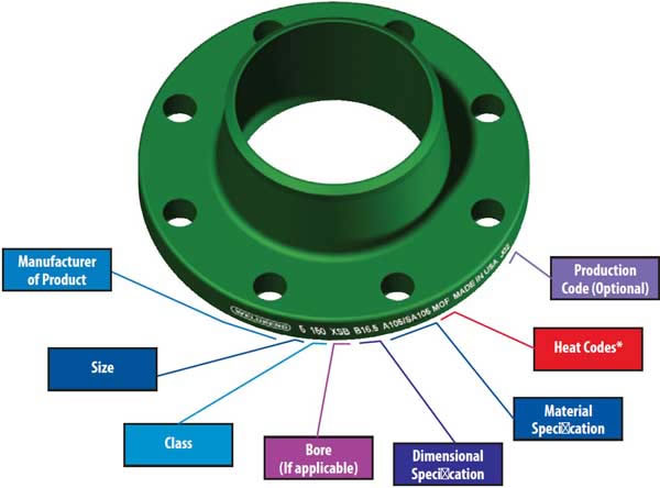
Flange markings are governed by ANSI ASME codes. Flange marking includes;
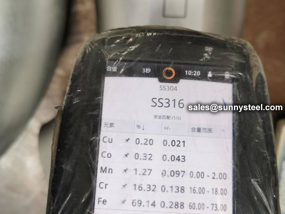
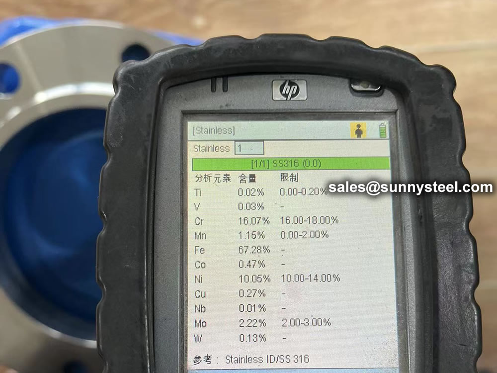
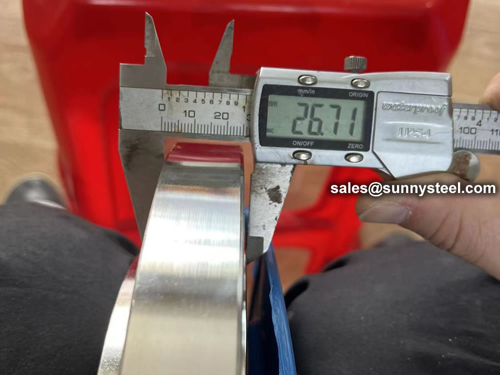
ASME B16.5 and B16.47 standards cover permissible tolerances for inspection.
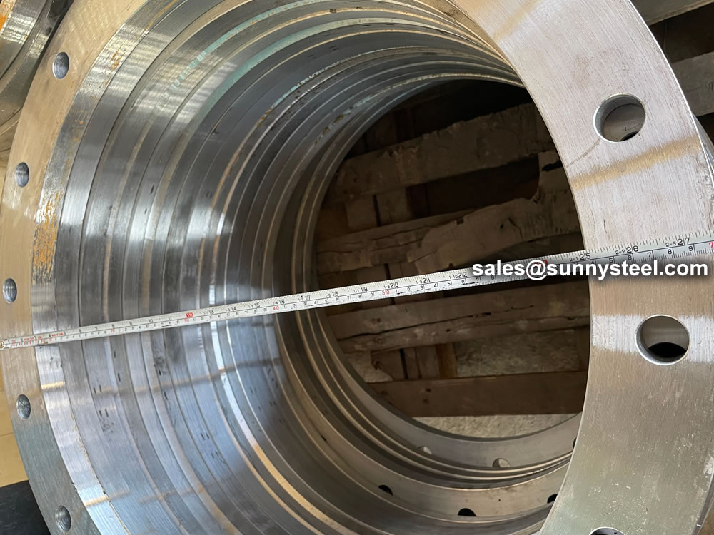
Because of the normal wooden boxes or wooden pallets have to do fumigation treatment, we usually use plywood pallet or plywood case or box to pack steel flanges without fumigation treatment.

When you partner with Sunny Steel, you can stop worrying about meeting deadlines thanks to our responsive and timely service. You'll also say goodbye to unnecessary shopping around. Instead, you'll get white glove service from an expert who understands your needs and can get you the materials you need quickly.
