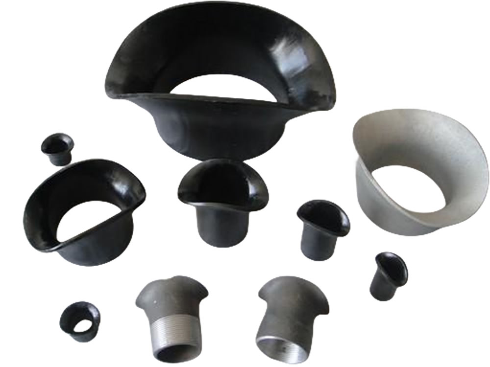
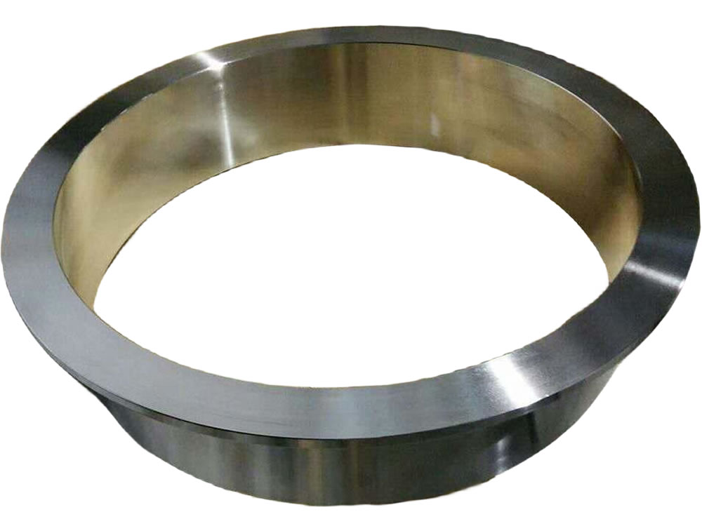
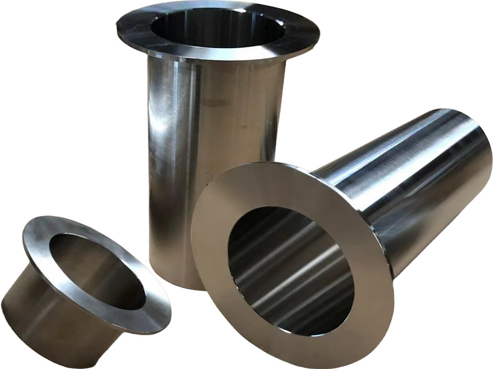
Pipe Collar
Pipe collars are connectors used to join pipes without welding, providing a secure and efficient piping solution.
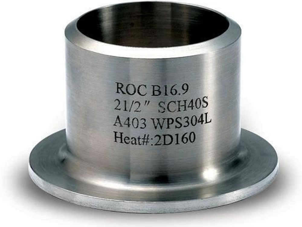
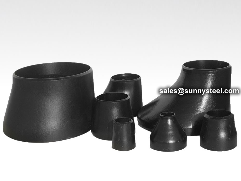
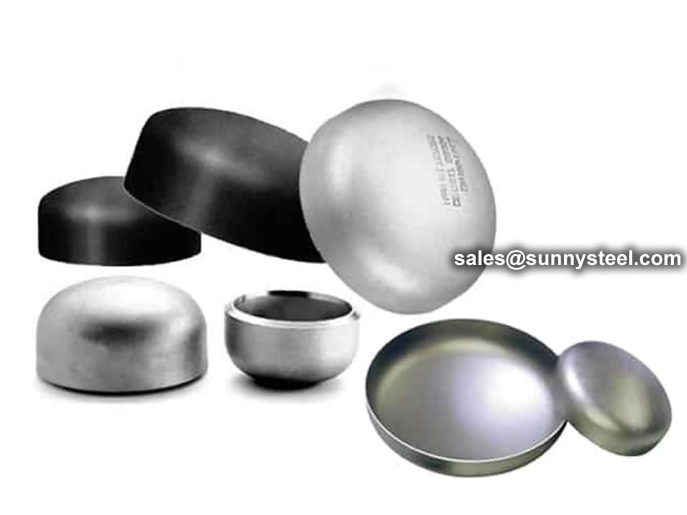
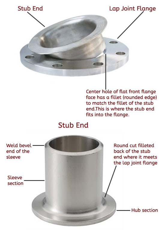
A stub end is a type of pipe fitting used in various industrial applications to connect pipes or flanges.
It is designed to be welded to the pipe or lap joint flange, providing a secure and leak-proof joint. The stub end itself does not have any threading; instead, it acts as a sleeve that slips over the pipe or lap joint flange. This unique design allows for easy and quick disassembly of the joint when needed.
Stub end are offered in three different ways, type A, B and C. Type A and B stub end are similar to forged fittings, such as elbows and tees, and type C stub end are made in customized sizes.
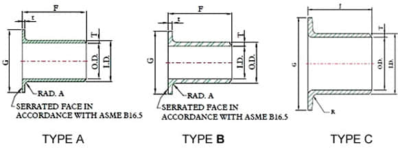
Stub ends are manufactured in three different types and two standard length.
Type “A”: this type is produced and machined to fit lap joint flanges.The mating surfaces of the stub end and the lap joint flange have a matching profile and surface. The lap thickness of type A stub ends is > = the minimum wall thickness of the connected pipe. The outside the stub end and the lap joint flange have a matching profile and surface. The lap thickness of type A stub ends is > = the minimum wall thickness of the connected pipe. The outside corner of type A has a radius to accommodate the lap join flange, whereas the inside corner is squared.
Type “B”: this type of stub ends is suited for standard slip-on flanges acting as lap-joint flanges. The lap thickness of type B stub ends is >= the minimum WT of the connecting pipe. The lap of these type of stub ends has generally a serrated face. To ensure tight joints, chamfers on the ID side of the flange are required.
Type “C”: this last type can be used both with lap joint and slip-on backing flanges and are fabricated out of pipes. The lap of C-type stub ends is flared over and the lap thickness is 75% of the connecting pipe WT. Type C has a short fillet outer radius able to host any back up flange.
Type “CS”: this type is similar to “C” with the difference that the lap face has concentric serrations machined during the manufacturing process.
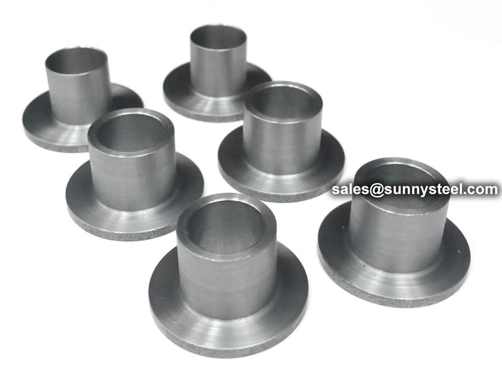
There are two main types of stub ends commonly used in piping systems:
Both long pattern and short pattern stub ends are available in various materials such as stainless steel, carbon steel, alloy steel, and others, making them suitable for different industrial applications. They provide a cost-effective and reliable solution for connecting pipes to flanges in piping systems.
Dimensions and manufacturing tolerances are covered in ASME B16.9 – Butt Weld Fittings and MSS-SP-43 (JIS B2312, JIS B2313 may also apply).
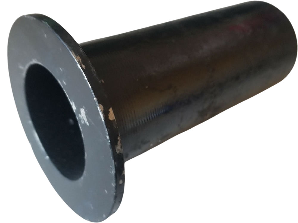
Stub End come in three standard lengths, MSS SP43 or ANSI B16.9 short and long pattern. Short pattern stub ends are mostly used for flanges from class 300 to class 600 and above. Besides these standard types, End-Users and contractors can require stub ends with non-standard lengths to suit specific project’s requirement. This will of course come at an additional cost.
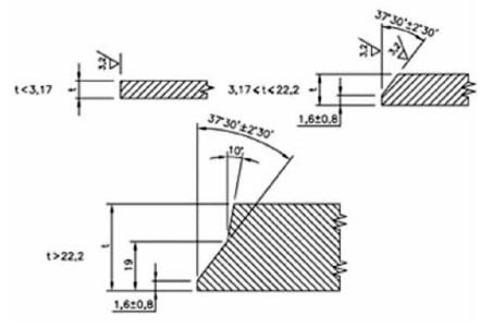
ASME B16.25 END WELDING BEVEL as right
The following types of ends may be ordered:
Beveled Ends (generally ASME B16.25)
Squared Ends
Flanged Ends
Victaulic Grooves
Threaded Ends (Male Only)


Pipe fitting dimensions are in either metric or Standard English.
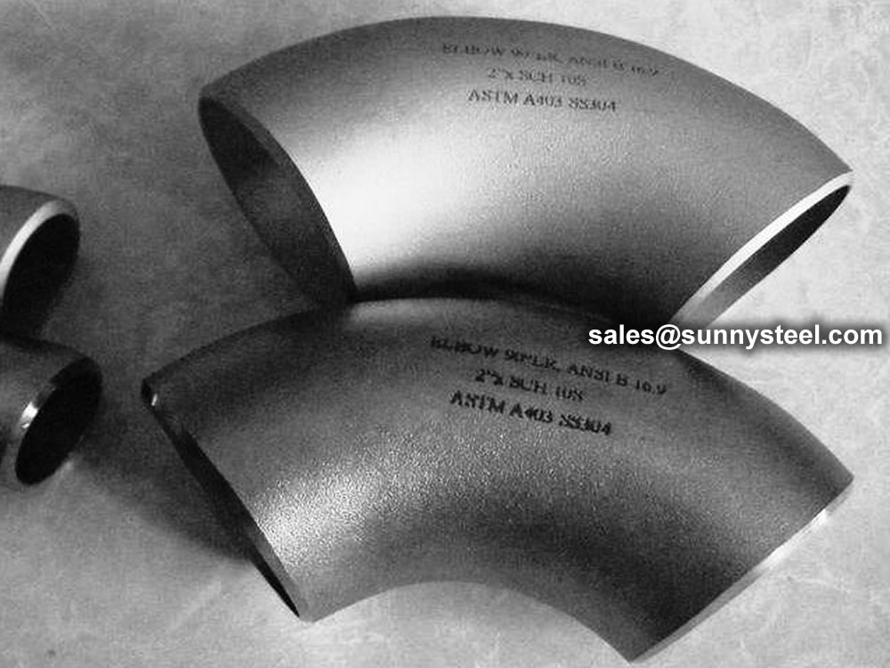
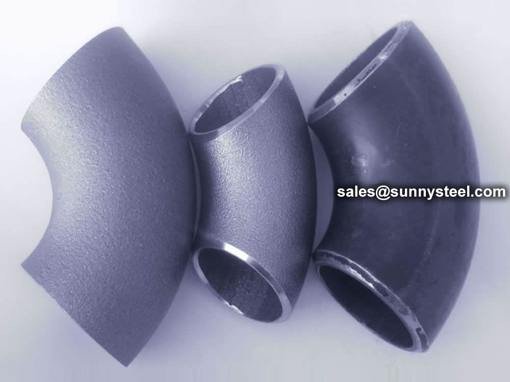
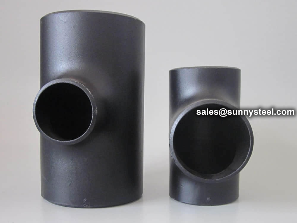
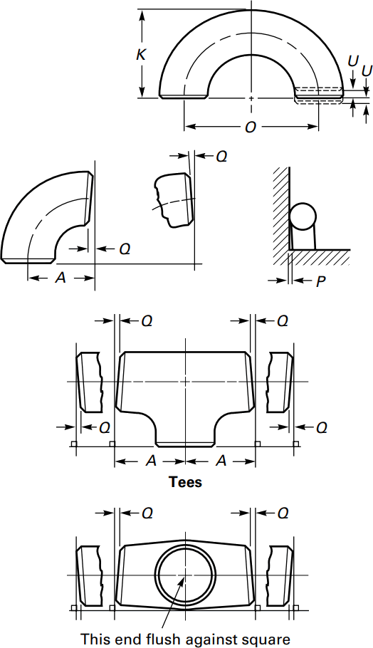
Because pipe fitting covers Pipe Fitting Dimensions several aspects, only the most common pipe fitting sizes can be given here. The most applied version is the 90° long radius and the 45° elbow, while the 90° short radius elbow is applied if there is too little space. The function of a 180° elbow is to change direction of flow through 180°. Both, the LR and the SR types have a center to center dimension double the matching 90° elbows. These fittings will generally be used in furnesses or other heating or cooling units.
Some of the standards that apply to buttwelded fittings are listed below. Many organizations such as ASME, ASTM, ISO, MSS, etc. have very well developed standards and specifications for buttwelded fittings. It is always up to the designer to ensure that they are following the applicable standard and company specification, if available, during the design process.
Some widely used pipe fitting standards are as follows:
This is one of the reputed organizations in the world developing codes and standards.
The schedule number for pipe fitting starts from ASME/ANSI B16. The various classifications of ASME/ANSI B16 standards for different pipe fittings are as follows:
This is one of the largest voluntary standards development organizations in the world. It was originally known as the American Society for Testing and Materials (ASTM).
AWWA About – Established in 1881, the American Water Works Association is the largest nonprofit, scientific and educational association dedicated to managing and treating water, the world’s most important resource.
ANSI is a private, non-profit organization. Its main function is to administer and coordinate the U.S. voluntary standardization and conformity assessment system. It provides a forum for development of American national standards. ANSI assigns "schedule numbers". These numbers classify wall thicknesses for different pressure uses.
The Manufacturers Standardization Society (MSS) of the Valve and Fittings Industry is a non-profit technical association organized for development and improvement of industry, national and international codes and standards for: Valves, Valve Actuators, Valve Modification, Pipe Fittings, Pipe Hangers, Pipe Supports, Flanges and Associated Seals
Piping codes imply the requirements of design, fabrication, use of materials, tests and inspection of various pipe and piping system. It has a limited jurisdiction defined by the code. On the other hand, piping standards imply application design and construction rules and requirements for pipe fittings like adapters, flanges, sleeves, elbows, union, tees, valves etc. Like a code, it also has a limited scope defined by the standard.
"Standards" on pipe fittings are based on certain factors like as follows:
BSP is the U.K. standard for pipe fittings. This refers to a family of standard screw thread types for interconnecting and sealing pipe ends by mating an external (male) with an internal (female) thread. This has been adopted internationally. It is also known as British Standard Pipe Taper threads (BSPT )or British Standard Pipe Parallel (Straight) threads (BSPP ). While the BSPT achieves pressure tight joints by the threads alone, the BSPP requires a sealing ring.
This is the Japanese industrial standards or the standards used for industrial activities in Japan for pipe, tube and fittings and published through Japanese Standards Associations.
National Pipe Thread is a U.S. standard straight (NPS) threads or for tapered (NPT) threads. This is the most popular US standard for pipe fittings. NPT fittings are based on the internal diameter (ID) of the pipe fitting.
We are manufacturer of Flange bolts & Nuts and supply high quality
The AN standard was originally designed for the U.S. Military. Whenever, a pipe fitting is AN fittings, it means that the fittings are measured on the outside diameter of the fittings, that is, in 1/16 inch increments.
For example, an AN 4 fitting means a fitting with an external diameter of approximately 4/16″ or ¼”. It is to be noted that approximation is important because AN external diameter is not a direct fit with an equivalent NPT thread.
Dash size is the standard used to refer to the inside diameter of a hose. This indicates the size by a two digit number which represents the relative ID in sixteenths of an inch. This is also used interchangeably with AN fittings. For example, a Dash "8" fitting means an AN 8 fitting.
ISO is the industrial pipe, tube and fittings standards and specifications from the International Organization for Standardization. ISO standards are numbered. They have format as follows:
"ISO[/IEC] [IS] nnnnn[:yyyy] Title" where
| Standard | Specification |
|---|---|
| ASTM A234 | Standard Specification for Piping Fittings of Wrought Carbon Steel and Alloy Steel for Moderate and High Temperature Service |
| ASTM A420 | Standard Specification for Piping Fittings of Wrought Carbon Steel and Alloy Steel for Low-Temperature Service |
| ASTM A234 WPB | ASTM A234 WPB refers to a specific grade of carbon steel pipe fittings, which are widely used in pressure piping and pressure vessel fabrication for service at moderate and elevated temperatures. |
| ASME B16.9 | ASME B16.9 Standard covers overall dimensions, tolerances,ratings, testing, and markings for factory-made wrought buttwelding fittings in sizes NPS 1⁄2 through NPS 48 (DN 15 through DN 1200). |
| ASME B16.28 | ASME B16.28 Standard covers ratings, overall dimensions, testing, tolerances, and markings for wrought carbon and alloy steel buttwelding short radius elbows and returns. |
| MSS SP-97 | MSS SP-97 Standard Practice covers essential dimensions, finish, tolerances, testing, marking, material, and minimum strength requirements for 90 degree integrally reinforced forged branch outlet fittings of buttwelding, socket welding, and threaded types. |
| ASTM A403 | Standard Specification for Wrought Austenitic Stainless Steel Piping Fittings. |
| DIN | EN | ASME |
|---|---|---|
| St 35.8 I St 35.8 III 15 Mo 3 13 CrMo 4 4 10 CrMo 9 10 St 35 N St 52.0 St 52.4 |
P235GH-TC1 P235GH-TC2 16Mo3 13CrMo4-5 10CrMo9-10 X10CrMoVNb9-1 P215NL P265NL L360NB L360NE P355N P355NL1 P355NH |
WPB WPL6 WPL3 WPHY 52 WP11 WP22 WP5 WP9 WP91 WP92 |
ASTM A234/A234M is a standard specification for piping fittings of wrought carbon steel and alloy steel for moderate and high-temperature service. This specification covers several grades of fittings that are used in various applications in the oil and gas, petrochemical, and power generation industries.
Download PDF| Grade | Type | C | Si | S | P | Mn | Cr | Ni | Mo | Other | ób | ós | δ5 |
|---|---|---|---|---|---|---|---|---|---|---|---|---|---|
| WPB | 0.3 | 0.1min | 0.058 | 0.05 | 0.29-1.06 | 0.4 | 0.4 | 0.15 | V:0.06;Nb:0.02 | 415-585 | 240 | 22 | 197 |
| WPC | 0.35 | 0.1min | 0.058 | 0.05 | 0.29-1.06 | 0.4 | 0.4 | 0.15 | V:0.06;Nb:0.02 | 485-655 | 275 | 22 | 197 |
| WP1 | 0.28 | 0.1-0.5 | 0.045 | 0.045 | 0.3-0.9 | 0.44-0.65 | 380-550 | 205 | 22 | 197 | |||
| WP12 CL1 | 0.05-0.2 | 0.6 | 0.045 | 0.045 | 0.3-0.8 | 0.8-1.25 | 0.44-0.65 | 415-585 | 220 | 22 | 197 | ||
| WP12 CL2 | 0.05-0.2 | 0.6 | 0.045 | 0.045 | 0.3-0.8 | 0.8-1.25 | 0.44-0.65 | 485-655 | 275 | 22 | 197 | ||
| WP11 CL1 | 0.05-0.15 | 0.5-1 | 0.03 | 0.03 | 0.3-0.6 | 1-1.5 | 0.44-0.65 | 415-585 | 205 | 22 | 197 | ||
| WP11 CL2 | 0.05-0.2 | 0.5-1 | 0.04 | 0.04 | 0.3-0.8 | 1-1.5 | 0.44-0.65 | 485-655 | 275 | 22 | 197 | ||
| WP11 CL3 | 0.05-0.2 | 0.5-1 | 0.04 | 0.04 | 0.3-0.8 | 1-1.5 | 0.44-0.65 | 520-690 | 310 | 22 | 197 | ||
| WP22 CL1 | 0.05-0.15 | 0.5 | 0.04 | 0.04 | 0.3-0.6 | 1.9-2.6 | 0.87-1.13 | 415-585 | 205 | 22 | 197 | ||
| WP22 CL3 | 0.05-0.15 | 0.5 | 0.04 | 0.04 | 0.3-0.6 | 1.9-2.6 | 0.87-1.13 | 520-690 | 310 | 22 | 197 | ||
| WP5 CL1 | 0.15 | 0.5 | 0.03 | 0.04 | 0.3-0.6 | 4-6 | 0.44-0.65 | 415-585 | 205 | 22 | 217 | ||
| WP5 CL3 | 0.15 | 0.5 | 0.03 | 0.04 | 0.3-0.6 | 4-6 | 0.44-0.65 | 520-690 | 310 | 22 | 217 | ||
| WP9 CL1 | 0.15 | 1 | 0.03 | 0.03 | 0.3-0.6 | 8-10 | 0.9-1.1 | 415-585 | 205 | 22 | 217 | ||
| WP9 CL3 | 0.15 | 1 | 0.03 | 0.03 | 0.3-0.6 | 8-10 | 0.9-1.1 | 520-690 | 310 | 22 | 217 | ||
| WPR | 0.2 | 0.05 | 0.045 | 0.4-1.06 | 1.6-2.24 | 435-605 | 315 | 22/28 | 217 | ||||
| WP91 | 0.08-0.12 | 0.2-0.5 | 0.01 | 0.02 | 0.3-0.6 | 8-9.5 | 0.4 | 0.85-1.05 | See sdandard | 585-760 | 415 | 20 | 248 |
| WP911 | 0.09-0.13 | 0.1-0.5 | 0.01 | 0.02 | 0.3-0.6 | 8.5-10.5 | 0.4 | 0.9-1.1 | See sdandard | 620-840 | 440 | 20 | 248 |
For each reduction of 0.01% below the specified C maximum, an increase of 0.06% Mn above the specified maximum will be permitted, up to a maximum of 1.35%.
The sum of Cu, Ni, Cr, and Mo shall not exceed 1.00%.
The sum of Cr and Mo shall not exceed 0.32%.
The maximum carbon equivalent (C.E.) shall be 0.50, based on heat analysis and the formula C.E.=C+Mn/6+(Cr+Mo+V)/5+(Ni+Cu)/15.
| Tensile Requirements | WPB | WPC, WP11CL2 | WP11CL1 | WP11CL3 |
|---|---|---|---|---|
| Tensile Strength, min, ksi[MPa] (0.2% offset or 0.5% extension-under-load) |
60-85 [415-585] |
70-95 [485-655] |
60-85 [415-585] |
75-100 [520-690] |
| Yield Strength, min, ksi[MPa] | 32 [240] |
40 [275] |
30 [205] |
45 [310] |
ASTM A403 Stainless Steel Pipe Fittings refers to the material of forged and rolled austenitic stainless fittings for pressure pipes. Common grades are WP304/L, WP316/L. They can be used into many fields as engineering industry, energy conversion plants etc.
ASTM A403 Standard specification covers the standard for wrought austenitic stainless steel fittings for pressure piping applications.
| Steel No. | Type | C | Si | S | P | Mn | Cr | Ni | Mo | Other | ób | ós | δ5 |
|---|---|---|---|---|---|---|---|---|---|---|---|---|---|
| WP304 | 0.08 | 1 | 0.03 | 0.045 | 2 | 18-20 | 8-11 | 515 | 205 | 28 | |||
| WP304H | 0.04-0.1 | 1 | 0.03 | 0.045 | 2 | 18-20 | 8-11 | 515 | 205 | 28 | |||
| WP304L | 0.035 | 1 | 0.03 | 0.045 | 2 | 18-20 | 8-13 | 485 | 170 | 28 | |||
| WP304LN | 0.03 | 0.75 | 0.03 | 0.045 | 2 | 18-20 | 8-10.5 | N2:0.1-0.16 | 515 | 205 | 28 | ||
| WP304N | 0.08 | 0.75 | 0.03 | 0.045 | 2 | 18-20 | 8-11 | N2:0.1-0.16 | 550 | 240 | 28 | ||
| WP309 | 0.15 | 1 | 0.03 | 0.045 | 2 | 22-24 | 12-15 | 515 | 205 | 28 | |||
| WP310 | 0.15 | 1.5 | 0.03 | 0.045 | 2 | 24-26 | 19-22 | 515 | 205 | 28 | |||
| WP316 | 0.08 | 1 | 0.03 | 0.045 | 2 | 16-18 | 10-14 | 2-3 | 515 | 205 | 28 | ||
| WP316H | 0.04-0.1 | 1 | 0.03 | 0.045 | 2 | 16-18 | 10-14 | 2-3 | 515 | 205 | 28 | ||
| WP316LN | 0.03 | 0.75 | 0.03 | 0.045 | 2 | 16-18 | 11-14 | 2-3 | N2:0.1-0.16 | 515 | 205 | 28 | |
| WP316L | 0.035 | 1 | 0.03 | 0.045 | 2 | 16-18 | 10-16 | 2-3 | 485 | 170 | 28 | ||
| WP316N | 0.08 | 0.75 | 0.03 | 0.045 | 2 | 16-18 | 11-14 | 2-3 | N2:0.1-0.16 | 550 | 240 | 28 | |
| WP317 | 0.08 | 1 | 0.03 | 0.045 | 2 | 18-20 | 11-15 | 3-4 | 515 | 205 | 28 | ||
| WP317L | 0.03 | 1 | 0.03 | 0.045 | 2 | 18-20 | 11-15 | 3-4 | 515 | 205 | 28 | ||
| WP321 | 0.08 | 1 | 0.03 | 0.045 | 2 | 17-20 | 9-13 | Ti:5C-0.7 | 515 | 205 | 28 | ||
| WP321H | 0.04-0.1 | 1 | 0.03 | 0.045 | 2 | 17-20 | 9-13 | Ti:4C-0.7 | 515 | 205 | 28 | ||
| WP347 | 0.08 | 1 | 0.03 | 0.045 | 2 | 17-20 | 9-13 | Nb+Ta:10C-1.1 | 515 | 205 | 28 | ||
| WP347H | 0.04-0.1 | 1 | 0.03 | 0.045 | 2 | 17-20 | 9-13 | Nb+Ta:8C-1 | 515 | 205 | 28 | ||
| WP348 | 0.08 | 1 | 0.03 | 0.045 | 2 | 17-20 | 9-13 | Ta:0.1 | 515 | 205 | 28 | ||
| WP348H | 0.04-0.1 | 1 | 0.03 | 0.045 | 2 | 17-20 | 9-13 | Ta:0.1 | 515 | 205 | 28 |
Notes:
For each reduction of 0.01% below the specified C maximum, an increase of 0.06% Mn above the specified maximum will be permitted, up to a maximum of 1.35%.
The sum of Cu, Ni, Cr, and Mo shall not exceed 1.00%.
The sum of Cr and Mo shall not exceed 0.32%.
The maximum carbon equivalent (C.E.) shall be 0.50, based on heat analysis and the formula C.E.=C+Mn/6+(Cr+Mo+V)/5+(Ni+Cu)/15.
| Grade | UNS | Tensile Strength, min | Yield Strength,min | Elongation min % in 4D | |||
|---|---|---|---|---|---|---|---|
| ksi | MPa | ksi | MPa | Longit % | Trans% | ||
| ALL | ALL | 75 | 515 | 30 | 205 | 28 | 20 |
| 304L | S30403 | 70 | 485 | 25 | 170 | 28 | 20 |
| 316L | S31603 | 70 | 485 | 25 | 170 | 28 | 20 |
| 304N | S30451 | 80 | 550 | 35 | 240 | 28 | 20 |
| 316N | S31651 | 80 | 550 | 35 | 240 | 28 | 20 |
| S31726 | 80 | 550 | 35 | 240 | 28 | 20 | |
| XM-19 | S20910 | 100 | 690 | 55 | 380 | 28 | 20 |
| S31254 | 94-119 | 650-820 | 44 | 300 | 28 | 20 | |
| S34565 | 115 | 795 | 60 | 415 | 28 | 20 | |
| S33228 | 73 | 500 | 27 | 185 | 28 | 20 | |
Material Furnished to this specification shall conform to the requirements of specifications A960/A960M including any supplementary requirements that are indicates in the purchase order. Failure to company with the common requirements of Specification A960/A960M constitutes non-conformance with this specification . In case of conflict between this specification and Specification A960/A960M , this specification shall prevail.
Material Furnished to this specification shall conform to the requirements of specifications A960/A960M including any supplementary requirements that are indicates in the purchase order. Failure to company with the common requirements of Specification A960/A960M constitutes non-conformance with this specification. In case of conflict between this specification and Specification A960/A960M , this specification shall prevail.
The standard includes several grades of austenitic stainless steel alloys, and uses the WP or CR prefix to mark the grade of steel, depending on the applicable ASTM or MSS size and rated pressure standards. ASTM A403 is designed for forged steel pipe fittings, Cast pipe fittings are not suitable.
| Elements | WPL6, % | WPL9, % | WPL3, % | WPL8, % |
|---|---|---|---|---|
| Carbon [C] | �?.30 | �?.20 | �?.20 | �?.13 |
| Manganese [Mn] | 0.50-1.35 | 0.40-1.06 | 0.31-0.64 | �?.90 |
| Phosphorus [P] | �?.035 | �?.030 | �?.05 | �?.030 |
| Sulfur [S] | �?.040 | �?.030 | �?.05 | �?.030 |
| Silicon [Si] | 0.15-0.40 | �?/td> | 0.13-0.37 | 0.13-0.37 |
| Nickel [Ni] | �?.40 | 1.60-2.24 | 3.2-3.8 | 8.4-9.6 |
| Chromium [Cr] | �?.30 | ... | ... | ... |
| Molybdenum [Mo] | �?.12 | ... | ... | ... |
| Copper [Cu] | �?.40 | 0.75-1.25 | �?/td> | �?/td> |
| Columbium [Cb] | �?.02 | ... | ... | ... |
| Vanadium[V] | �?.08 | ... | ... | ... |
*For grade WPL6, the limit for Columbium may be increased up to 0.05% on heat analysis and 0.06% on product analysis.
*Fittings of WPL3 made from plate or forgings may have 0.90 % max manganese.
*Fittings of WPL8 made from plate may have 0.98 % max manganese.
| ASTM A420/ A420M | Tensile Strength, min. | Yield Strength, min. | Elongation %, min | |||
|---|---|---|---|---|---|---|
| Grade | ksi | MPa | ksi | MPa | Longitudinal | Transverse |
| WPL6 | 65-95 | 415-655 | 35 | 240 | 22 | 12 |
| WPL9 | 63-88 | 435-610 | 46 | 315 | 20 | �?/td> |
| WPL3 | 65-90 | 450-620 | 35 | 240 | 22 | 14 |
| WPL8 | 100-125 | 690-865 | 75 | 515 | 16 | �?/td> |
*All the elongation values are on the basis of standard round specimen, or small proportional specimen, min % in 4 D.
ASTM A234 is Standard Specification for steel pipe fittings includes carbon and alloy steel material for moderate and high temperature services.
ASME B16.9 Standard covers overall dimensions, tolerances,ratings, testing, and markings for factory-made wrought buttwelding fittings in sizes NPS 1⁄2 through NPS 48 (DN 15 through DN 1200).
Download PDF| Nominal | Outside Diameter | 90° Elbows | 45° Elbows | 180° Returns | ||||
|---|---|---|---|---|---|---|---|---|
| Pipe Size |
Long Radius | Short Radius | Long Radius | Long Radius | ||||
| (inches) | (mm) | (inches) | Center to Face | Center to Face | Center to Face | Radius | Center to Center | Back to face |
| (inches) | (inches) | (inches) | (inches) | (inches) | (inches) | |||
| 1/2 | 21.3 | 0.84 | 1.5 | – | 5/8 | 2 | 1.875 | |
| 3/4 | 26.7 | 1.05 | 1.125 | – | 7/16 | 2.25 | 1.6875 | |
| 1 | 33.4 | 1.315 | 1.5 | 1 | 7/8 | 3 | 2.1875 | |
| 1.25 | 42.2 | 1.66 | 1.875 | 1.25 | 1 | 3.75 | 2.75 | |
| 1.5 | 48.3 | 1.9 | 2.25 | 1.5 | 1.125 | 3 | 4.5 | 3.25 |
| 2 | 60.3 | 2.375 | 3 | 2 | 1.375 | 4 | 6 | 4.1875 |
| 2.5 | 73 | 2.875 | 3.75 | 2.5 | 1.75 | 5 | 7.5 | 5.1875 |
| 3 | 88.9 | 3.5 | 4.5 | 3 | 2 | 6 | 9 | 6.25 |
| 3.5 | 101.6 | 4 | 5.25 | 3.5 | 2.25 | 7 | 10.5 | 7.25 |
| 4 | 114.3 | 4.5 | 6 | 4 | 2.5 | 8 | 12 | 8.25 |
| 5 | 141.3 | 5.563 | 7.5 | 5 | 3.125 | 10 | 15 | 10.3125 |
| 6 | 168.3 | 6.625 | 9 | 6 | 3.75 | 12 | 18 | 12.3125 |
| 8 | 219.1 | 8.625 | 12 | 8 | 5 | 12 | 24 | 16.3125 |
| 10 | 273.1 | 10.75 | 15 | 10 | 6.25 | 15 | 30 | 20.375 |
| 12 | 323.9 | 12.75 | 18 | 12 | 7.5 | 18 | 36 | 24.375 |
| NOMINAL PIPE SIZE NPS | ANGULARITY TOLERANCES | ANGULARITY TOLERANCES |
|---|---|---|
| Size | Off Angle Q | Off Plane P |
| ½ to 4 | 0.03 | 0.06 |
| 5 to 8 | 0.06 | 0.12 |
| 10 to 12 | 0.09 | 0.19 |
| 14 to 16 | 0.09 | 0.25 |
| 18 to 24 | 0.12 | 0.38 |
| 26 to 30 | 0.19 | 0.38 |
| 32 to 42 | 0.19 | 0.5 |
| 44 to 48 | 0.18 | 0.75 |
All dimensions are given in inches. Tolerances are equal plus and minus except as noted.
The ASME B16.9 pipe fittings can be used under the jurisdiction of the ASME Boiler & Pressure Vessel Code (BPVC) as well as the ASME Code for pressure piping. Referencing pressure ratings of flanges per ASME B16.5, they can be designated as Classes 150, 300, 600, 900, 1500 and 2500. The allowable pressure ratings for ASME B16.9 pipe fittings may be calculated as for straight seamless pipe of equivalent material in accordance with the rules established in the applicable sections of ASME B31 Code for pressure piping.
The design of butt welding pipe fittings made to ASME B16.9 shall be established by one of the following methods: (a) mathematical analyses contained in pressure vessel or piping codes; (b) proof testing; (c) experimental stress analysis with hydrostatic testing to validate experimental results; (d) detailed stress analysis with results evaluation.
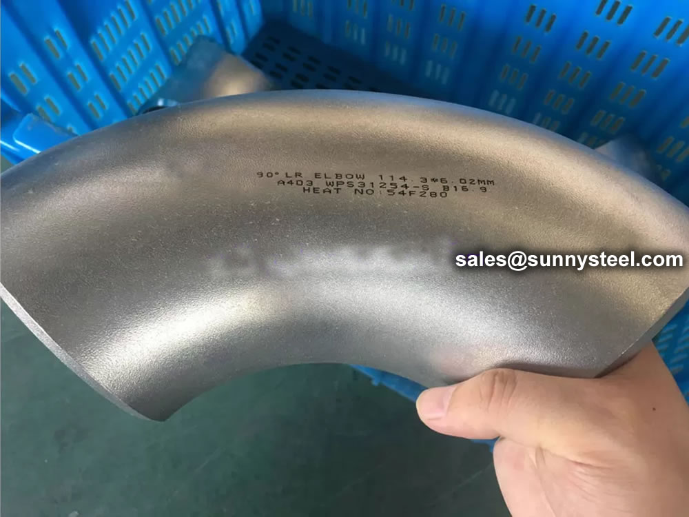
Generally, ASME B16.9 pipe fittings shall be marked to show the following details: “trademark + material grade + wall thickness + size + heat number”. For example, “M ASTM A234 WP5 SCH80 6″ 385“. When steel stamps are used, care shall be taken so that
the marking is not deep enough or sharp enough to cause cracks or to reduce the wall thickness of the fitting below the minimum allowed.
The ASME B16.9 fittings may be made from an extensive range of mateirals covering (1) carbon and low-alloy steels in accordance with ASTM A234 and ASTM A420; (2) austenitic and duplex stainless steels in accordance with ASTM A403 and ASTM A815; (3) nickel alloys in accordance with ASTM B366; (4) aluminum alloys in accordance with ASTM B361; and (5) titanium alloys in accordance with ASTM B363.
Sizes 1/2″ – 48″
MSS SP-97 Standard Practice covers essential dimensions, finish, tolerances, testing, marking, material, and minimum strength requirements for 90 degree integrally reinforced forged branch outlet fittings of buttwelding, socket welding, and threaded types.
| Elements | Value, % |
|---|---|
| Carbon (C) | ≤0.30 |
| Manganese (Mn) | ≤1.60 |
| Phosphorus (P) | ≤0.035 |
| Sulfur (S) | ≤0.035 |
| Copper (Cu) | ≤0.50 |
| Nickel (Ni) | ≤0.50 |
| Silicon (Si) | ≤0.50 |
| Chromium (Cr) | ≤0.25 |
| Molybdenum (Mo) | ≤0.13 |
| Vanadium (V) | ≤0.13 |
| Columbium (Cb) | ≤0.10 |
| Titanium(Ti) | ≤0.05 |
*1. The sum of Cu, Ni, Cr and Mo shall not exceed 1%.
*2. Carbon equivalent C.E.=C+Mn/6+(Cr+Mo+V)/5+(Ni+Cu)/15 shall not exceed 0.45%.
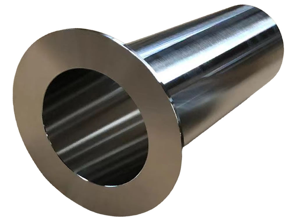
Stub ends are essential components used in various industrial applications, particularly in piping systems.
The use of stub ends has these two advantages:
Reduces the overall cost of the flanged joint Generally, the lap joint flange is of a lower grade than the material of the stub end and the pipework, thus saving the total weight of high-grade material used for the flanged joint.
Reduces the overall cost of the flanged joint
Generally, the lap joint flange is of a lower grade than the material of the stub end and the pipework, thus saving the total weight of high-grade material used for the flanged joint.
Example:
For an SS316 pipe, instead of using a full 316 welding neck flange, a combination of an SS316 stub end and a carbon steel lap joint flange would do the same exact job, but the total weight of SS316 material would be lower, and the cost as well.
Essentially, stub ends allow to minimize the weight of high-grade material in stainless, duplex, and nickel alloy piping, saving costs. Of course, the bigger the diameter and the class of the flanges, the higher the saving!
Commercial advantages are that the Stub End, will be wetted and it must be made of a grade of material that meets the process design and service conditions of the pipeline. However, the Lap Flange is un-wetted and it can be made of a lower grade of material as long as it meets the mechanical strength requirements of the piping systems.
The “loose” Flange concept of a Lap Joint, is very beneficial during field installation of piping systems. If two spools are to be mated up in the field, having one Flange that can be rotated is very advantageous when aligning the bolt holes, prior to the introduction of the Stub bolt and the accompanying nuts. The facility of easier orientation and alignment of bolt holes, is of particular use it there is a spool that has to be removed frequently, if positive isolation is a process requirement.
While stub ends offer numerous advantages in piping systems, it's essential to also consider their limitations. Being aware of these limitations helps engineers, designers, and operators make informed decisions when selecting fittings for specific applications. Let's explore some of the key limitations associated with stub ends:
Stub ends, particularly those used in lap joint flange connections, often have lower pressure ratings compared to fully welded or threaded alternatives. This limitation makes them unsuitable for high-pressure applications.
Stub ends are typically made from materials that can be easily formed and welded, such as stainless steel and carbon steel. However, they may not be compatible with certain materials like exotic alloys or non-metallic materials.
In applications where there is significant vibration, movement, or mechanical stress, stub ends may not provide the same level of reliability as fully welded connections. The slip-on design could potentially lead to loosening or disconnection.
Unlike fully welded joints, stub ends rely on the lap joint flange for connection strength. This means the joint's integrity is dependent on the quality of the flange and the fasteners used.
Due to the gapped design between the pipe end and the flange, there is a risk of leakage, especially when dealing with fluids or gases under pressure. The joint might require additional sealing measures to prevent leaks.
Certain materials used for stub ends may not withstand extremely high temperatures, limiting their application in industries where elevated temperatures are common.
Stub ends might limit axial pipe movement and thermal expansion compared to fully flexible joints. This could impact the system's ability to accommodate changes in temperature or pressure.
The effectiveness of stub ends relies on the quality of the lap joint flange and the proper installation of fasteners. Any issues with flange quality or installation can compromise the joint's integrity.
For applications where a secure and leak-proof connection is paramount, such as those involving hazardous or toxic substances, fully welded joints may be preferred over stub ends.
Stub ends can be harder to inspect and maintain compared to fully welded joints, as visual assessment of the joint's condition may be limited due to the slip-on design.
Stub ends, particularly those made from certain materials, may not be suitable for use in environments with severe corrosion or aggressive chemical exposure.
In conclusion, while stub ends offer various advantages, they also come with specific limitations that need to be carefully considered during the selection and design of piping systems. Engineers and operators should evaluate the specific requirements of each application and assess whether the benefits of using stub ends outweigh their limitations. By making informed decisions, industries can ensure safe, reliable, and efficient piping networks that meet the demands of their operational environments.
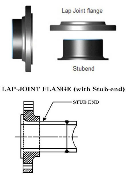
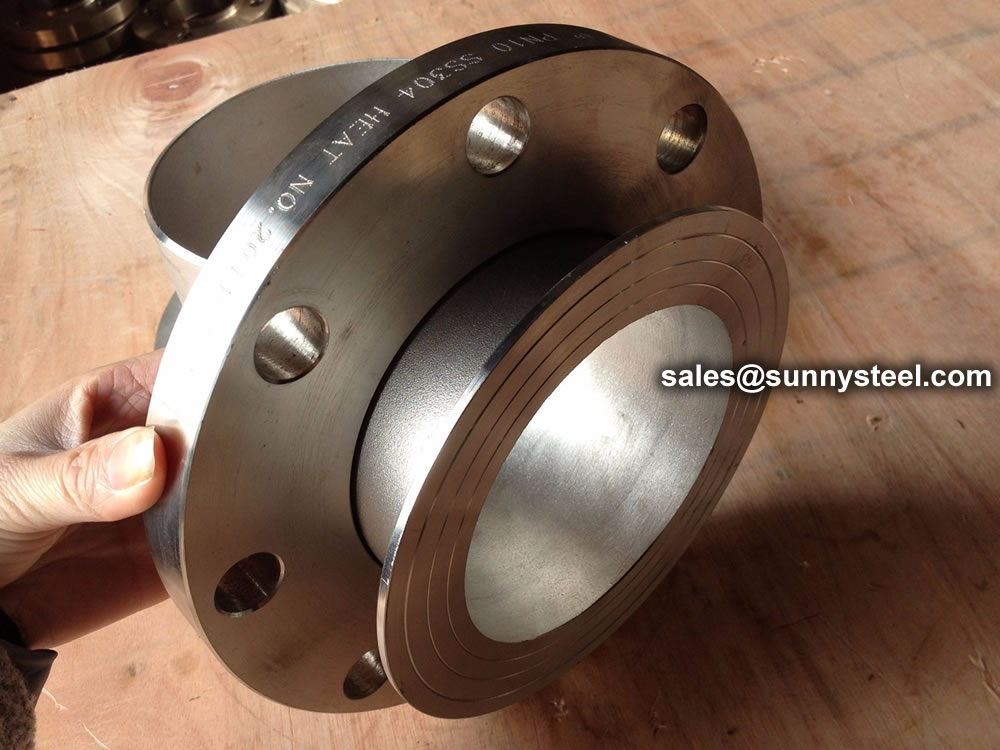
A stud end and a lap joint flange can be used together as an alternative way to make a flanged connection than welding neck flanges.
Using a stud end and a lap joint flange provides an alternative method for creating a flanged connection, different from welding neck flanges.
The components involved are:
This approach offers flexibility and ease of assembly, making it a valuable alternative to traditional welding neck flanges.
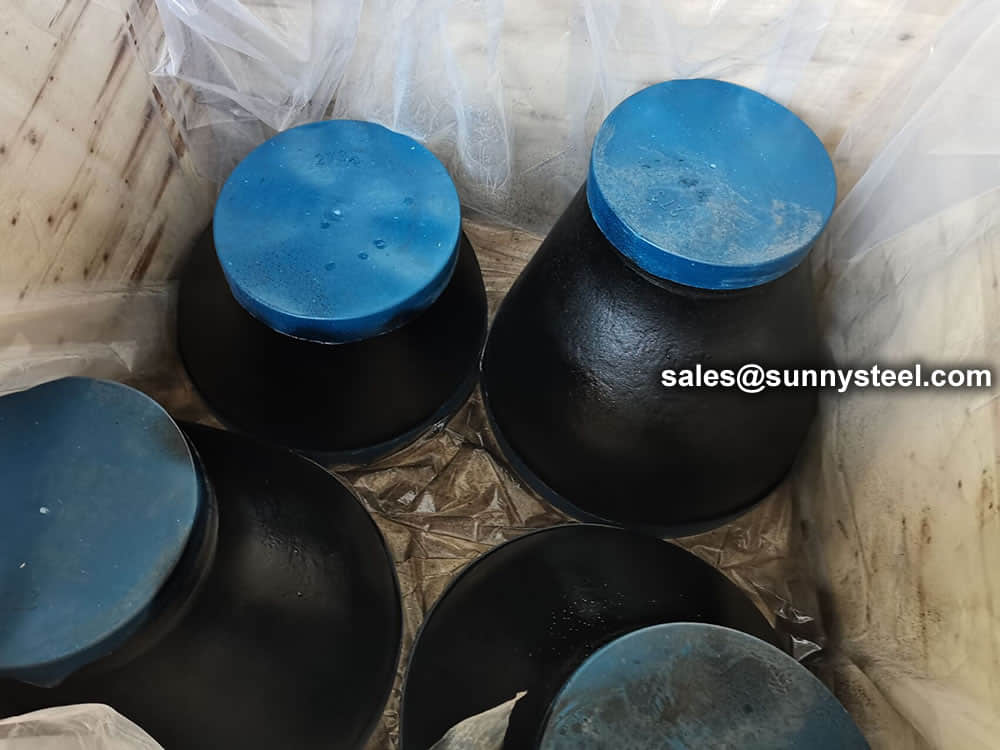
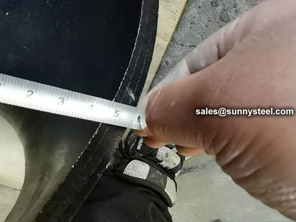
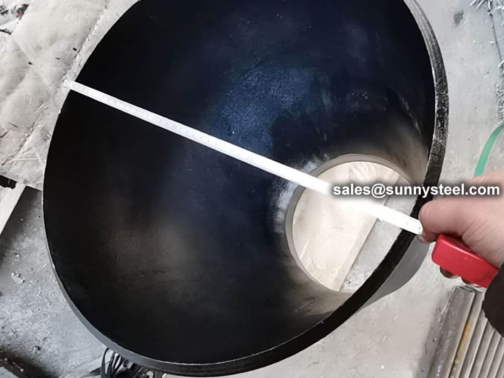
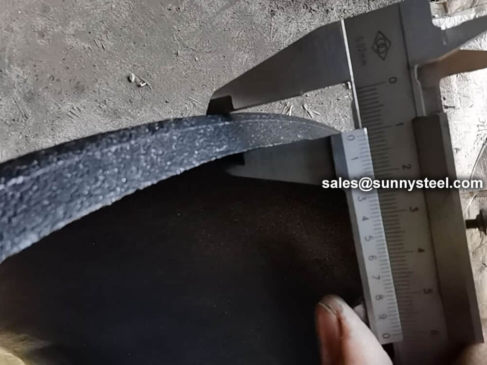
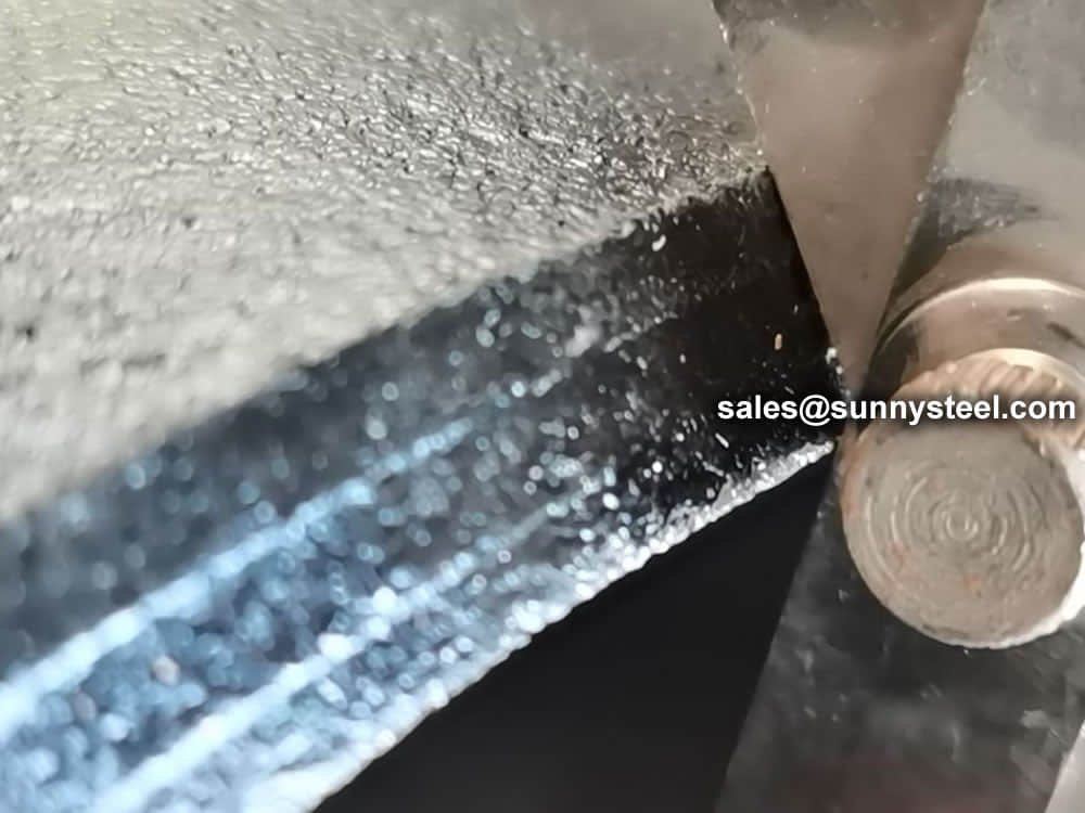
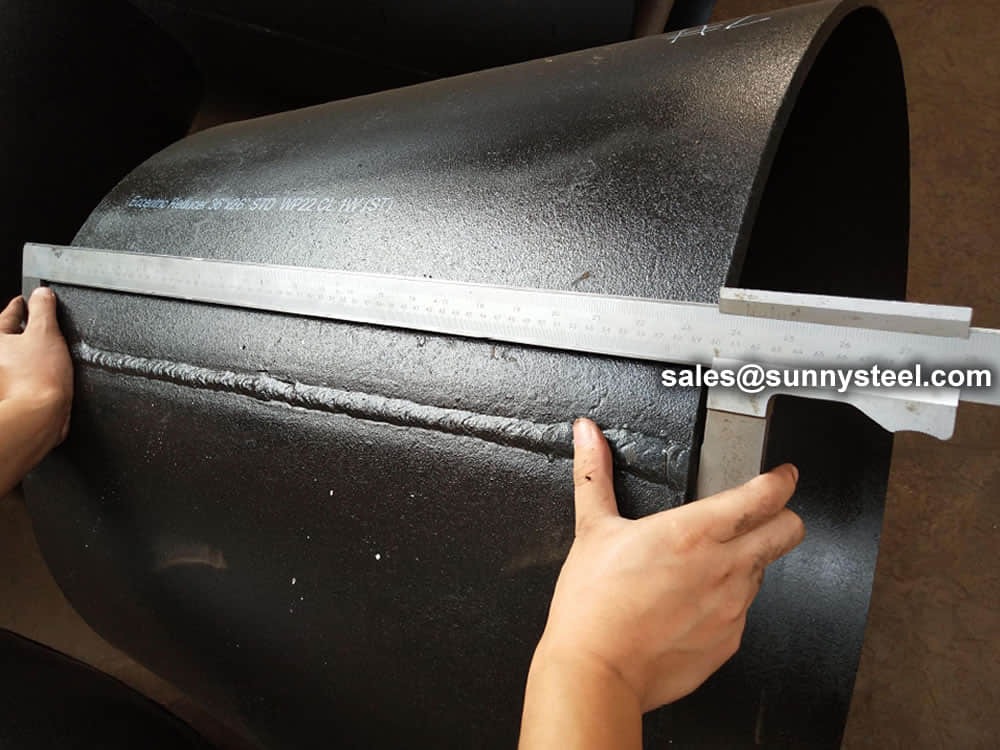
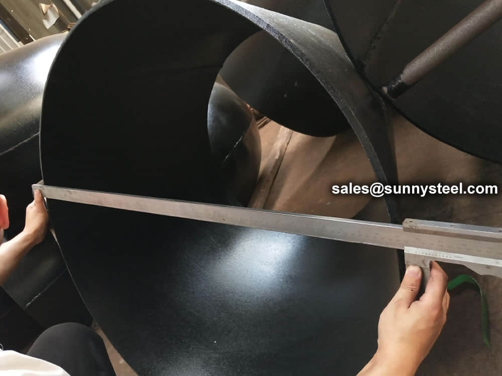
Visual Inspection is conducted on fittings to check any surface imperfections. Both fittings body and weld are checked for any visible surface imperfections such as dents, die marks, porosity, undercuts, etc. Acceptance as per applicable standard.
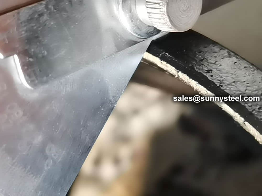
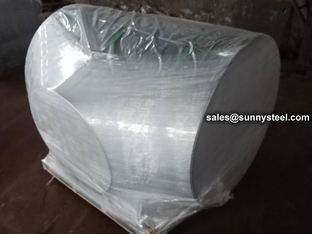
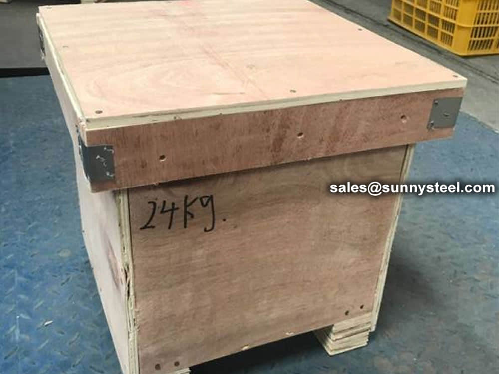
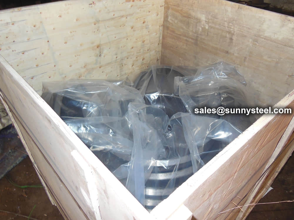
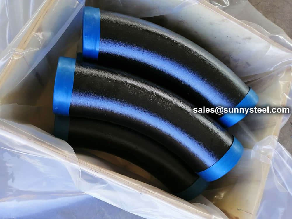
For packing of carbon steel flanges with painting,we would use the bubble wrap to protect the painting.For flanges without painting or oiled with long-term shipment,we would suggest client to use the anti-tarnish paper and plastic bag to prevent the rust.

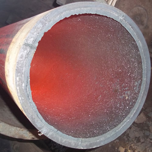
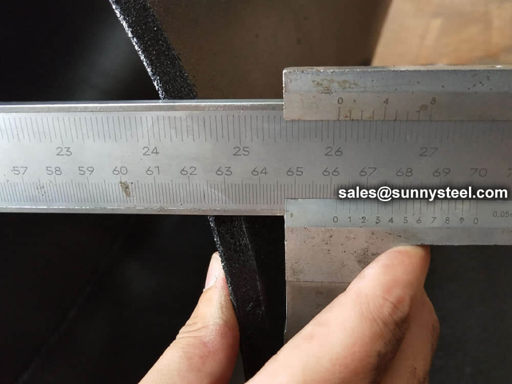
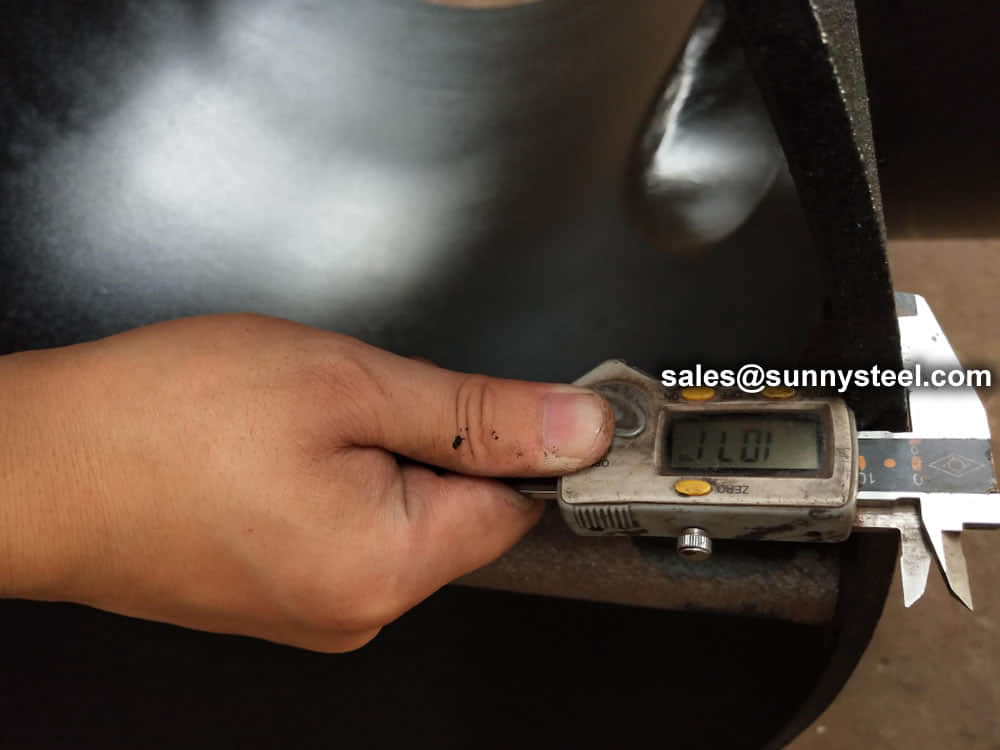
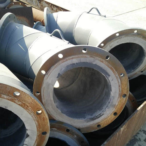
Ceramic lined pipe is made through self-propagating high-temperature synthesis (SHS) technique.
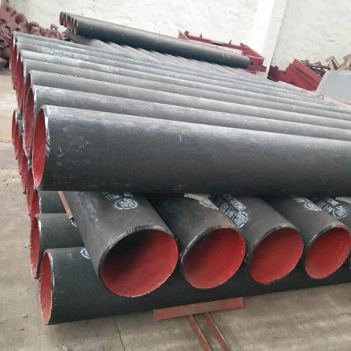
Cast basalt lined steel pipe is composed by lined with cast basalt pipe, outside steel pipe and cement mortar filling between the two layers.
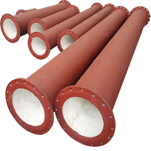
Ceramic tile lined pipes have very uniform coating of specially formulated ceramic material that is affixed to the inner of the pipe.
The material of the rare earth alloy wear-resistant pipe is ZG40CrMnMoNiSiRe, which is also the grade of rare earth alloy steel.
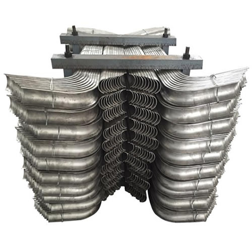
Tubes Erosion Shields are used to protect boiler tubing from the highly erosive effects of high temperatures and pressures thereby greatly extending tube life.
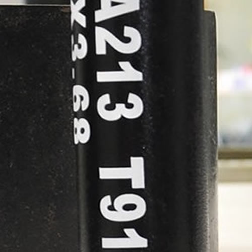
The ASTM A213 T91 seamless tubes are primarily used for boiler, superheater, and heat-exchanger.

When you partner with Sunny Steel, you can stop worrying about meeting deadlines thanks to our responsive and timely service. You'll also say goodbye to unnecessary shopping around. Instead, you'll get white glove service from an expert who understands your needs and can get you the materials you need quickly.