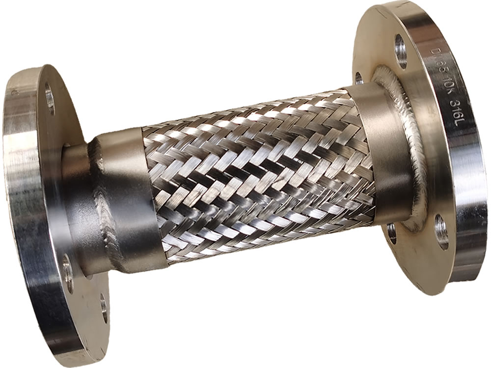
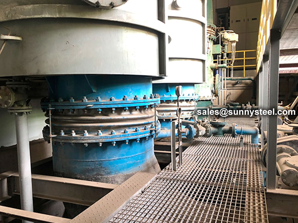
Welded Bellows Pump Connectors
Durable welded bellows connectors for reliable pump applications.
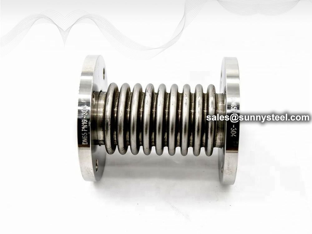
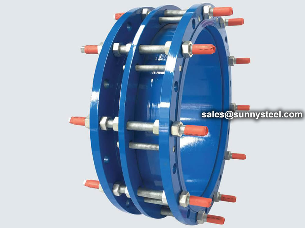
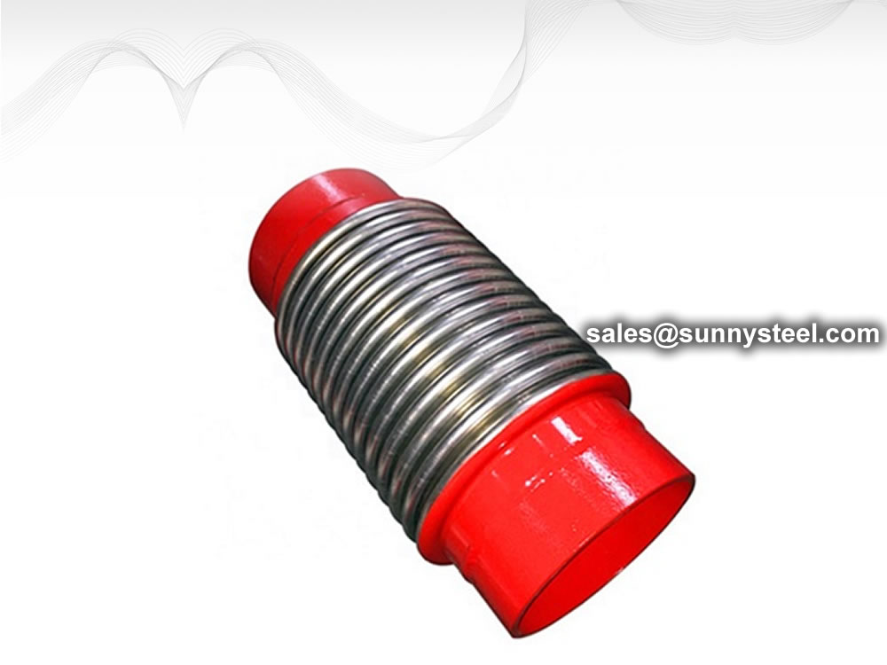
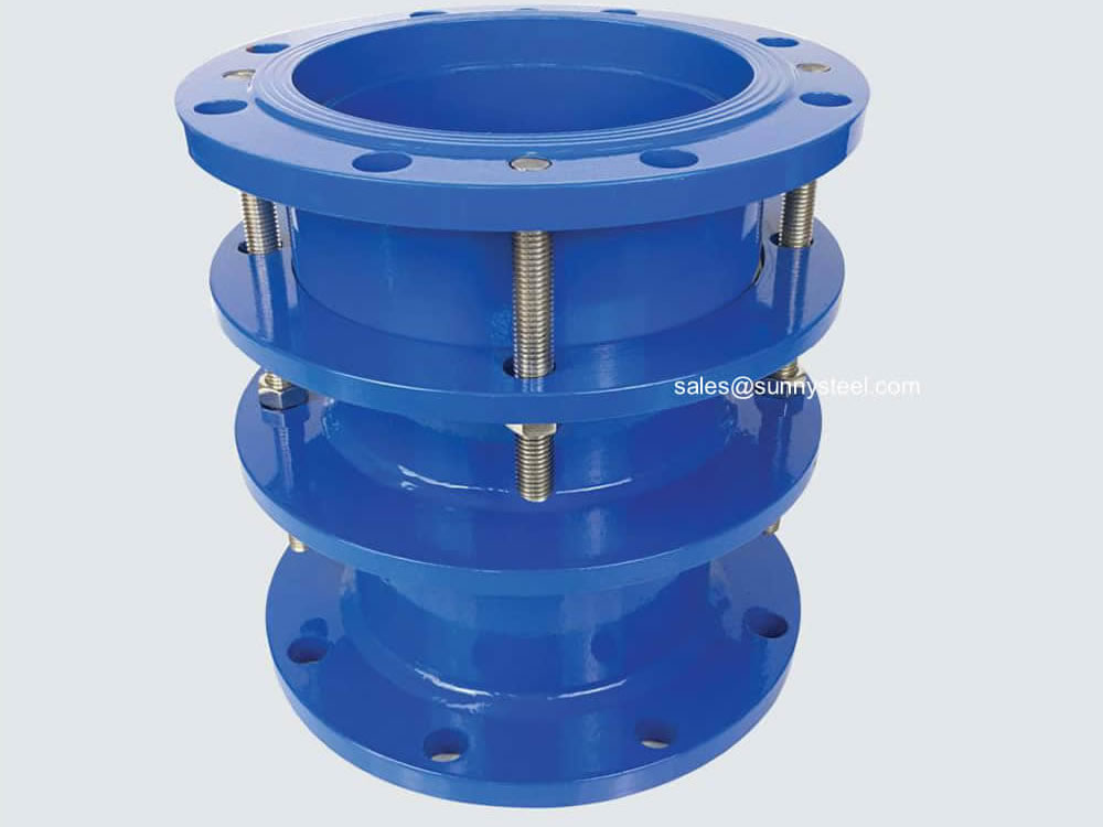
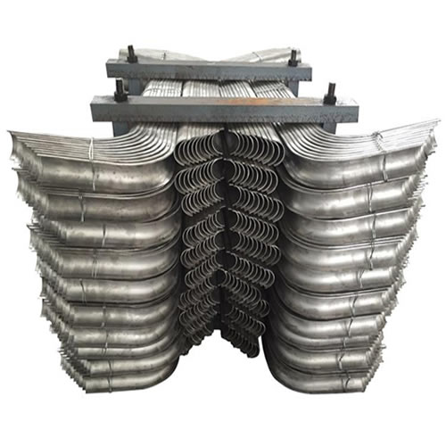
The groove type bellow expansion joint is a compensating element.
Download PDFThe groove type bellow expansion joint also called a clamp type bellows expansion joint. The groove type bellow expansion joint is a compensating element. Using the effective telescopic deformation of the corrugated pipe of the working body to absorb the dimensional changes caused by thermal expansion and contraction of pipelines, pipes, containers, etc., for compensating for axial, lateral and angular displacement of pipelines, pipes, vessels, etc. For example: a new type of special grooved type bellow for fire protection.
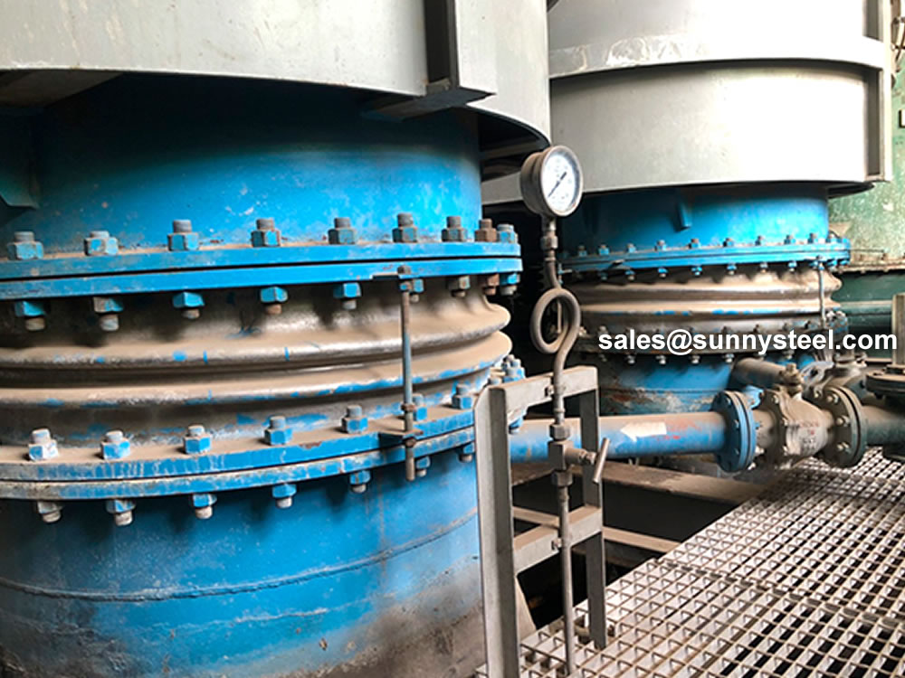
The groove is connected to the grooved type bellow and the process is very simple and requires no special expertise. A pipe connection takes only a few minutes, which simplifies the technical difficulty of on-site operation and saves man-hours, thus stabilizing project quality, improving work efficiency and reducing labor costs.
Grooved type bellow, only in the connected nozzle tube groove, without damaging the thickness of the tube wall, which is a technical advantage unique to the grooved type bellow process. The groove-connected bellow has a unique flexibility, which makes the pipeline anti-vibration, anti-shrinkage and expansion. Compared with welding and flange connection, the stability of the piping system can be enhanced, which is more suitable for temperature changes. This protects pipes, valves and equipment and also reduces damage to components by pipe stresses.
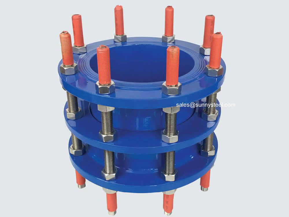
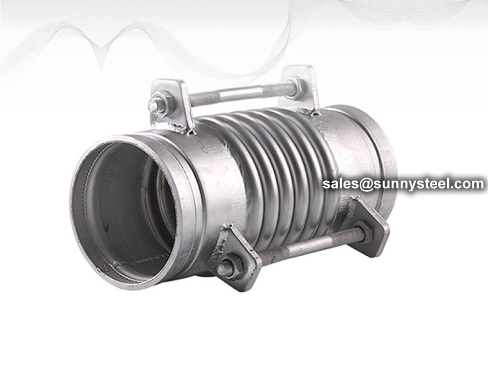
Flange-connected metal hoses need to be paired with flanges, bolts, gaskets, and installation time. The grooved metal fittings do not have these fittings, which greatly reduces engineering costs. Used mostly in fire lines and water lines.
The grooved type bellow is simple for connecting the grooved pipe fittings, and the required operating space is small, which brings many convenient conditions for future maintenance. When the pipeline and valve equipment need to be repaired or replaced, just loosen the two groove clamps to replace, rotate, and modify a section of the pipeline. No need to damage surrounding walls, reducing repair time and maintenance costs.
| Nominal diameter DN |
Quantity of ripple | Pressure level(Mpa) | Effective area of corrugated tube (cm2) |
Maximum external diameter size (mm) |
Length Connection tube (mm) |
||||
|---|---|---|---|---|---|---|---|---|---|
| 0.25 | 0.6 | 1 | 1.6 | 2.5 | |||||
| Axial compensation (mm),f911 degree N/ram | |||||||||
| 32 | 8 | 25/21 | 22/26 | 20/26 | 18/63 | 15/98 | 16 | 110 | 264/210 |
| 16 | 50/11 | 46/14 | 41/14 | 36/32 | 31/47 | 220 | 316/320 | ||
| 40 | 8 | 25/28 | 22/44 | 20/44 | 18/89 | 15/106 | 23 | 130 | 269/260 |
| 16 | 50/14 | 46/22 | 41/22 | 36/45 | 31/55 | 240 | 319/400 | ||
| 50 | 8 | 25/30 | 22/51 | 20/70 | 18/70 | 15/138 | 37 | 150 | 282/230 |
| 16 | 50/16 | 46/26 | 41/35 | 36/35 | 31/70 | 260 | 347/450 | ||
| 65 | 8 | 33/28 | 30/35 | 26/44 | 22/55 | 19/68 | 55 | 170 | 300/260 |
| 12 | 42/16 | 38/22 | 38/32 | 34/40 | 29/50 | 280 | 340/470 | ||
| 80 | 8 | 40/20 | 36/26 | 34/33 | 28/41 | 24/54 | 81 | 200 | 344/260 |
| 10 | 53/14 | 49/17 | 49/21 | 43/26 | 38/33 | 230 | 374/300 | ||
| 100 | 8 | 45/47 | 45/60 | 40/75 | 35/93 | 29/117 | 121 | 220 | 323/280 |
| 10 | 76/26 | 74/32 | 64/40 | 57/50 | 49/63 | 260 | 387/320 | ||
| 125 | 6 | 48/38 | 42/47 | 38/59 | 34/74 | 29/92 | 180 | 250 | 316/320 |
| 8 | 85/23 | 77/29 | 66/36 | 58/45 | 50/56 | 290 | 388/360 | ||
| 150 | 6 | 49/42 | 44/50 | 40/62 | 34/78 | 29/97 | 257 | 250 | 338/320 |
| 8 | 79/34 | 71/43 | 64/51 | 54/59 | 46/65 | 290 | 402/360 | ||
| 200 | 6 | 52/49 | 46/55 | 42/68 | 38/78 | 34/111 | 479 | 300 | 348/370 |
| 8 | 73/31 | 65/44 | 59/52 | 53/58 | 48/78 | 340 | 402/420 | ||
| 250 | 6 | 72/30 | 63/34 | 59/42 | 52/45 | 47/55 | 769 | 300 | 415/420 |
| 8 | 108/16 | 97/21 | 87/35 | 79/39 | 71/47 | 360 | 493/460 | ||
| 300 | 6 | 72/51 | 65/55 | 59/59 | 52/65 | 47/71 | 1105 | 340 | 466/488 |
| 8 | 108/32 | 97/35 | 87/37 | 79/41 | 71/45 | 400 | 564/520 | ||
| 350 | 6 | 72/58 | 65/62 | 59/67 | 52/74 | 47/81 | 1307 | 340 | 497/480 |
| 8 | 108/38 | 97/41 | 87/44 | 79/48 | 71/47 | 420 | 609/540 | ||
| 400 | 6 | 72/54 | 65/58 | 59/62 | 52/68 | 47/75 | 1611 | 340 | 512/480 |
| 8 | 108/36 | 97/39 | 87/43 | 79/47 | 71/52 | 420 | 622/560 | ||
| 450 | 6 | 108/32 | 97/35 | 87/37 | 79/41 | 71/45 | 1972 | 340 | 503/500 |
| 8 | 162/20 | 145/22 | 131/23 | 118/25 | 106/28 | 450 | 603/590 | ||
| 500 | 6 | 108/59 | 97/64 | 87/68 | 79/75 | 71/82 | 2445 | 340 | 531/500 |
| 8 | 162/34 | 145/37 | 131/39 | 118/43 | 106/48 | 450 | 631/600 | ||
| 600 | 6 | 108/74 | 97/80 | 87/85 | 79/94 | 71/103 | 3534 | 380 | 578/540 |
| 8 | 162/42 | 145/45 | 131/49 | 118/53 | 106/60 | 758/640 | |||
| 700 | 4 | 108/67 | 97/72 | 87/77 | 79/85 | 71/103 | 4717 | 1110 | 550 |
| 6 | 162/42 | 145/45 | 131/49 | 118/53 | 106/60 | 670 | |||
| 800 | 4 | 120/88 | 102/95 | 102/102 | 94/112 | 71/95 | 5822 | 1265 | 560 |
| 6 | 183/67 | 164/72 | 156/77 | 144/85 | 106/60 | 600 | |||
| 900 | 4 | 120/84 | 108/90 | 102/97 | 94/107 | 82/123 | 7620 | 1186 | 620 |
| 6 | 183/60 | 164/65 | 156/69 | 144/76 | 125/93 | 720 | |||
| 1000 | 4 | 120/91 | 108/98 | 102/105 | 94/116 | 82/117 | 9043 | 1286 | 690 |
| 6 | 183/59 | 164/65 | 156/71 | 144/81 | 125/84 | 790 | |||
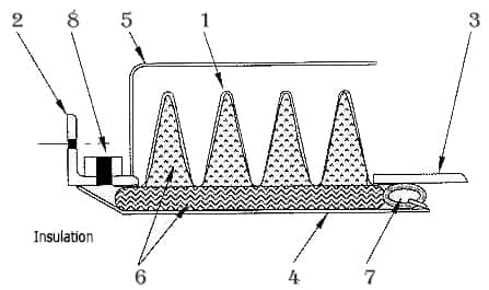
Accessories are added to an expansion joint installation to meet specific customer, application or code requirements. Some are used to control movement, others to protect the bellows in the event of pressure thrust, and still others to defend against corrosion caused by media inside or from the environment outside the bellows.
Divide piping into two separate segments insuring proper movement of each bellows in double type expansion joint.
Used in conjunction with internal sleeve to:
Internal liners can be used to either protect the metallic bellows from erosion or reduce turbulence across the bellows. They must be used when purge connectors are included in the design. In order to provide enough clearance in the liner design, appropriate lateral and angular movements must be specified by the designer. When designing an expansion joint with combination ends, flow direction must be specified as well.
External covers should be used to protect the internal bellows from being damaged. They also serve a purpose as insulation of the bellows. Covers can either be designed as removable or permanent accessories.
In systems that have a media with significant particulate content (i.e. flash or catalyst), a barrier of ceramic fiber can be utilized to prevent corrosion and restricted bellows flexibility resulting from the accumulation of the particulate. Purge connectors may also be utilized to perform this same function. Internal liners must also be included in the design if the expansion joint includes purge connectors or particulate barriers.
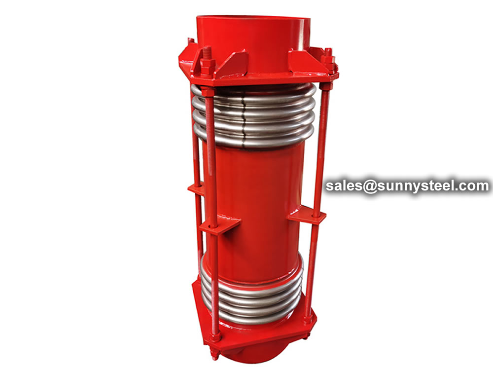
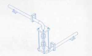
Limit rods may be used in an expansion joint design to limit the axial compression or expansion. They allow the expansion joint to move over a range according to where the nut stops are placed along the rods. Limit rods are used to prevent bellows over-extension while restraining the full pressure thrust of the system.
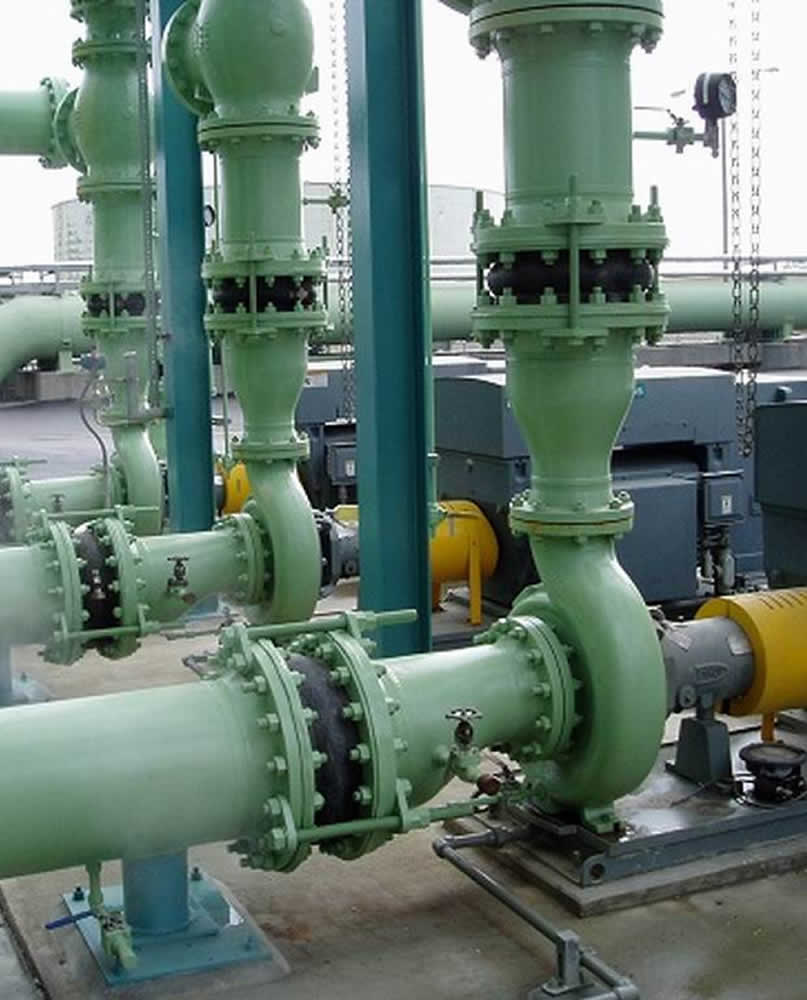
Pipe expansion joints are necessary in systems that convey high temperature commodities such as steam or exhaust gases, or to absorb movement and vibration.
An expansion joint is a useful component in an infinite number of applications.
A bellows is made up of a series of one or more convolutions, with the shape of the convolution designed to withstand the internal pressures of the pipe, but flexible enough to accept the axial, lateral, and/or angular deflections.
Expansion joints are also designed for other criteria, such as noise absorption, anti-vibration, earthquake movement, and building settlement.
Engineers and pipe designers routinely incorporate expansion joints into their pipe systems, as expansion joints add flexibility in to the design and reduce costs through removing the complexity of fix points, guides and reduces the overall space requirements for the pipe system.
Further, expansion joints are more effective than alternatives such as pipe bends and pipe loops due to their greater ability to conserve space, their economic efficiency and better performance in absorbing larger movements.
An expansion joint is a useful component in an infinite number of applications. Metal expansion joint assemblies are commonly used for all kinds of industries and applications including:
Expansion joints are often installed near boilers, heat exchangers, pumps, turbines, condensers, engines and in long pipe systems or pipe ducts.
Expansion joints come in a wide variety of designs. Some of them are standard and some are customised as per client requirements.
Although their design may vary significantly, all expansion joints are nevertheless composed from some of the following components, all with one or more specific functionalities: bellows, welding ends, flanges, hinges, tie-rods, spherical washers, wire mesh, insulation, inner sleeve, external cover, elbow and/or ring reinforcement/equalizing rings.
In general, there are fabric, metallic, and rubber expansion joints.
In a piping system a Expansion joints alternately known as Bellows are like sealed springs. Sealed because it is required to contain the fluid pressure which is flowing through it and spring because it is required to respond to the movement of the connected piping without offering appreciable stiffness to the piping system.
The Bellows are generally employed in a piping system in one of the following situations:
An expansion joint or movement joint is an assembly designed to safely absorb the heat-induced expansion and contraction of construction materials, to absorb vibration, to hold parts together, or to allow movement due to ground settlement or earthquakes.
They are commonly found between sections of buildings, bridges, sidewalks, railway tracks, piping systems, ships, and other structures.
Expansion joints sometimes called expansion bellows, flexible joints or Expansion joint are devices that comprise of a flexible element known as the bellows membrane that is fitted to end connections that are best suited to the pipework they are to be installed in.
Most bellows membranes are manufactured from stainless steel and are made up of a series of convolutions manufactured to withstand the pressure of the system but also must be suitable to accept the movements for which they are designed. The bellows membrane comprises of a series of convolutions designed to withstand the internal pressures of the system, but at the same time flexible enough to accept axial, lateral and angular deflections.
The joint needs to be a highly resistant nature so it’s necessary to make sure that it’s far thicker than you’d expect. In turn, this slows down any effects of potential corrosion as although it may be affected by the elements over time, it will still retain its density.
Expansion joints are required in large ducted air systems to allow fixed pieces of piping to be largely free of stress as thermal expansion occurs.
Bends in elbows also can accommodate this.
Expansion joints also isolate pieces of equipment such as fans from the rigid ductwork thereby reducing vibration to the ductwork as well as allowing the fan to “grow” as it comes up to the operating air system temperature without putting stress on the fan or the fixed portions of ductwork.
An expansion joint is designed to allow deflection in the axial(compression) or laterally (shear) or angular (bending) deflections. Expansion joints can be non-metallic or metallic (often called bellows type). Non-metallic can be a single ply of rubberized material or a composite made of multiple layers of heat and erosion resistant flexible material.
Typical layers are: outer cover to act a gas seal, a corrosion resistant material such as Teflon, a layer of fiberglass to act as an insulator and to add durability, several layers of insulation to ensure that the heat transfer from the flue gas is reduced to the required temperature and an inside layer.
A bellows is made up of a series of one or more convolutions of metal to allow the axial, lateral or angular deflection required.
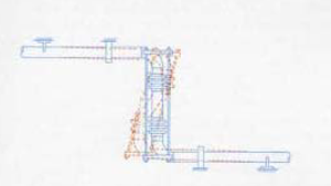
Tied universal expansion joints are frequently used to absorb lateral deflection in a "Z bend configuration. The expansion joint absorbs the thermal movement of horizontal pipelines as lateral deflection. This can be accomplished in a single plane or three plane configuration. In a three plane "Z bend the horizontal pipes may lie at any angle in the horizontal plane since the tied universal expansion joint can absorb lateral deflection in any direction.
Expansion joints are used in all kinds of different sectors and in a huge range of different industrial contexts.
Specific industries that use expansion joints include the Energy sector such as nuclear power plants and district heating schemes.
Essentially, wherever there is a need to control pipework movement expansion joints are required. They are used in factories and power plants wherever thermal expansion needs to be controlled, such as pipelines that connect with condensers or power turbines. They are used in oil and fuel gas applications.
The Petrochemical industry on oil refineries, pumping stations and oil rigs.
Civil engineering, waste management, sewage treatment, recycling, water treatment, aerospace, aviation, defence, the automotive industry, agriculture, mining, metals manufacturing, food and dairy manufacturing and packaging, and so on.
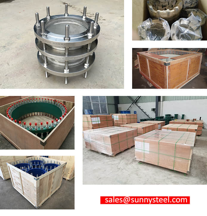
Inner plastic film packing, outer standard export wooden case packing.
Courier company transport, air freight and sea transport. It depends on your actual order details and quantity.

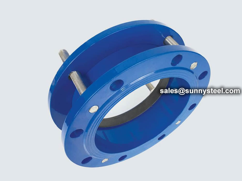
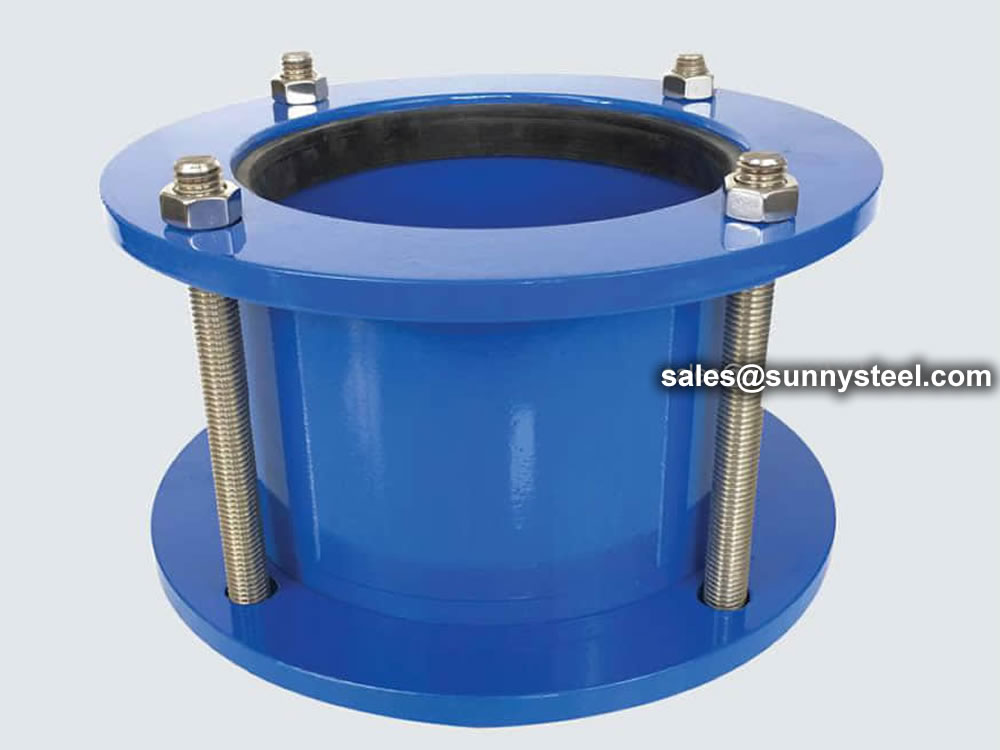
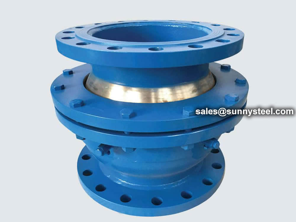
Double flanged joints for secure and reliable pipe expansion compensation.

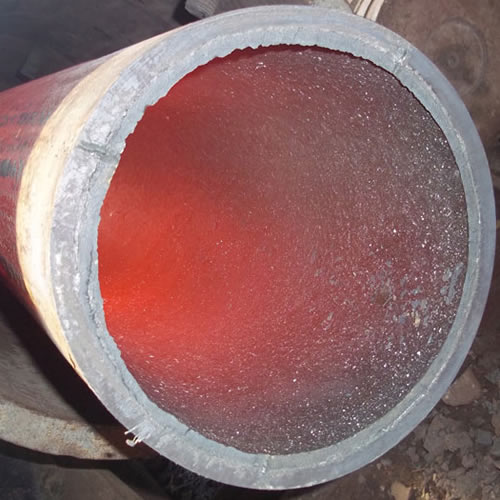
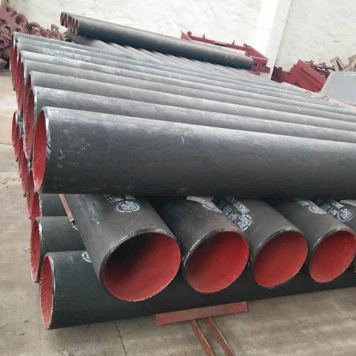
Ceramic lined pipe is made through self-propagating high-temperature synthesis (SHS) technique.
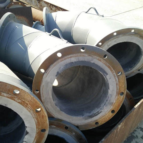
Cast basalt lined steel pipe is composed by lined with cast basalt pipe, outside steel pipe and cement mortar filling between the two layers.
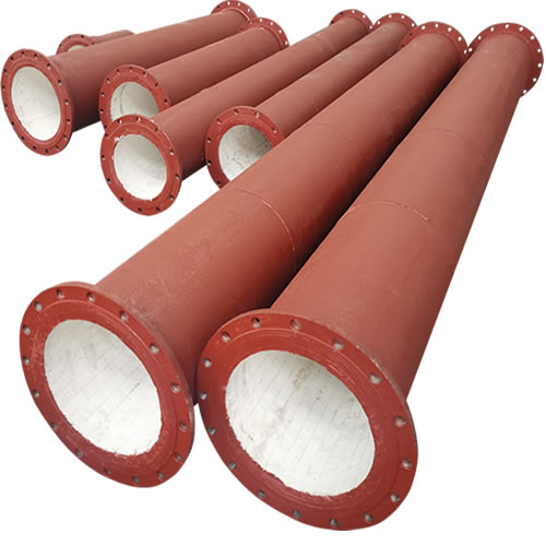
Ceramic tile lined pipes have very uniform coating of specially formulated ceramic material that is affixed to the inner of the pipe.
The material of the rare earth alloy wear-resistant pipe is ZG40CrMnMoNiSiRe, which is also the grade of rare earth alloy steel.
Tubes Erosion Shields are used to protect boiler tubing from the highly erosive effects of high temperatures and pressures thereby greatly extending tube life.
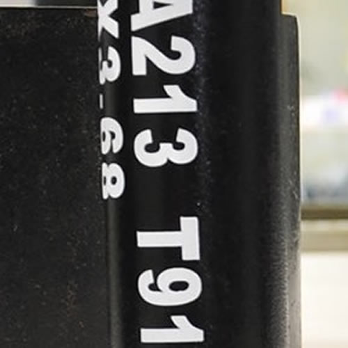
The ASTM A213 T91 seamless tubes are primarily used for boiler, superheater, and heat-exchanger.

When you partner with Sunny Steel, you can stop worrying about meeting deadlines thanks to our responsive and timely service. You'll also say goodbye to unnecessary shopping around. Instead, you'll get white glove service from an expert who understands your needs and can get you the materials you need quickly.