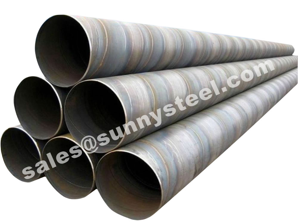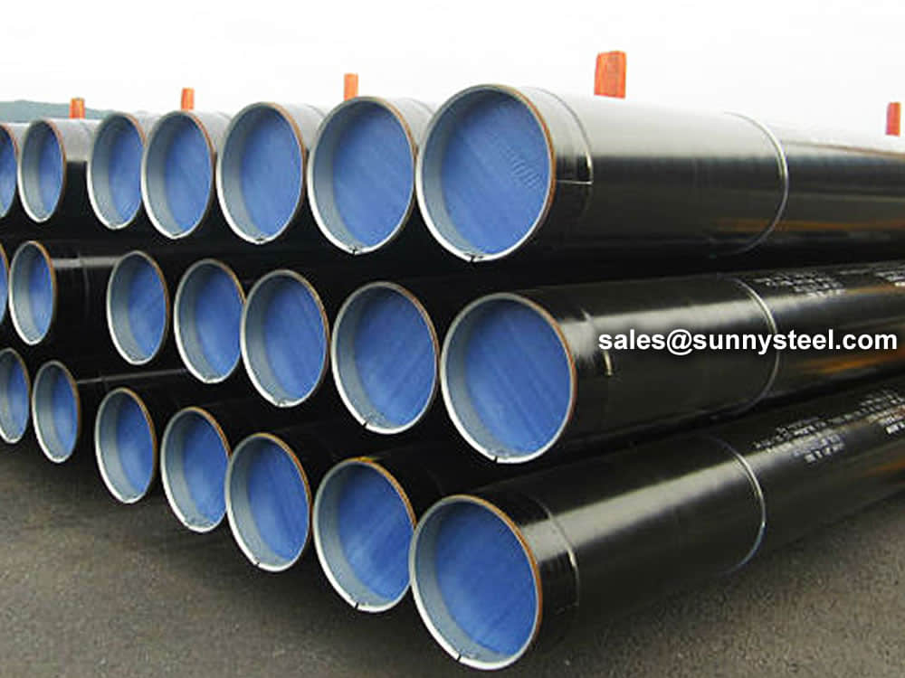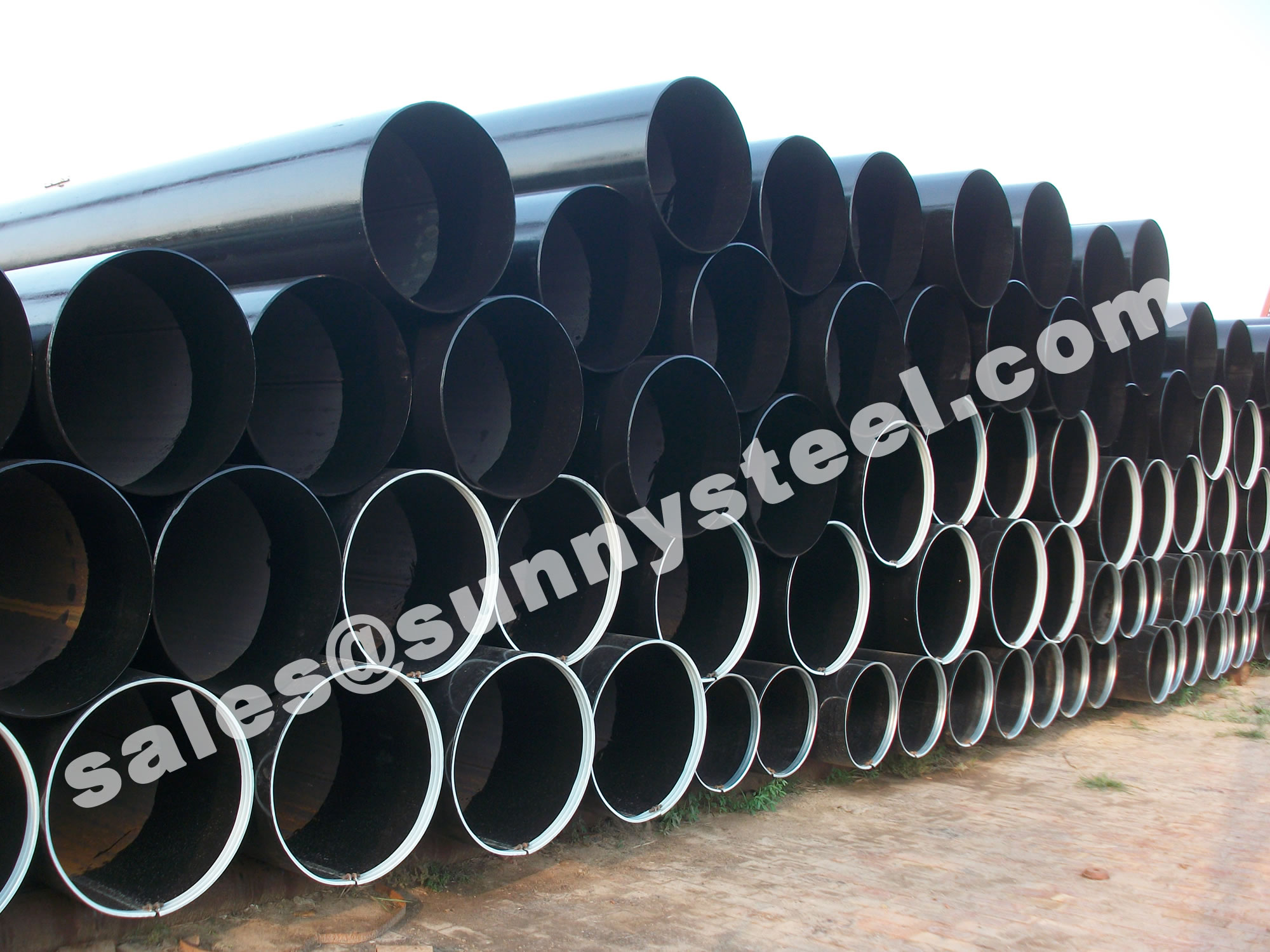
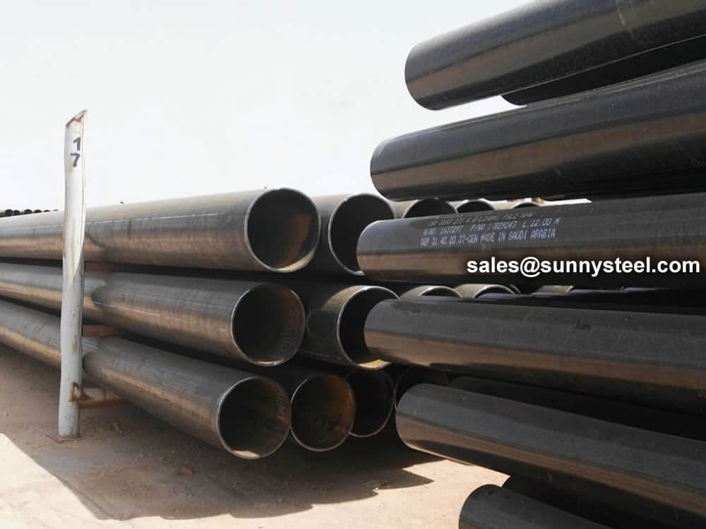
EFW Pipe
Electric Fusion Welded (EFW) pipes known for their uniform quality and strength.
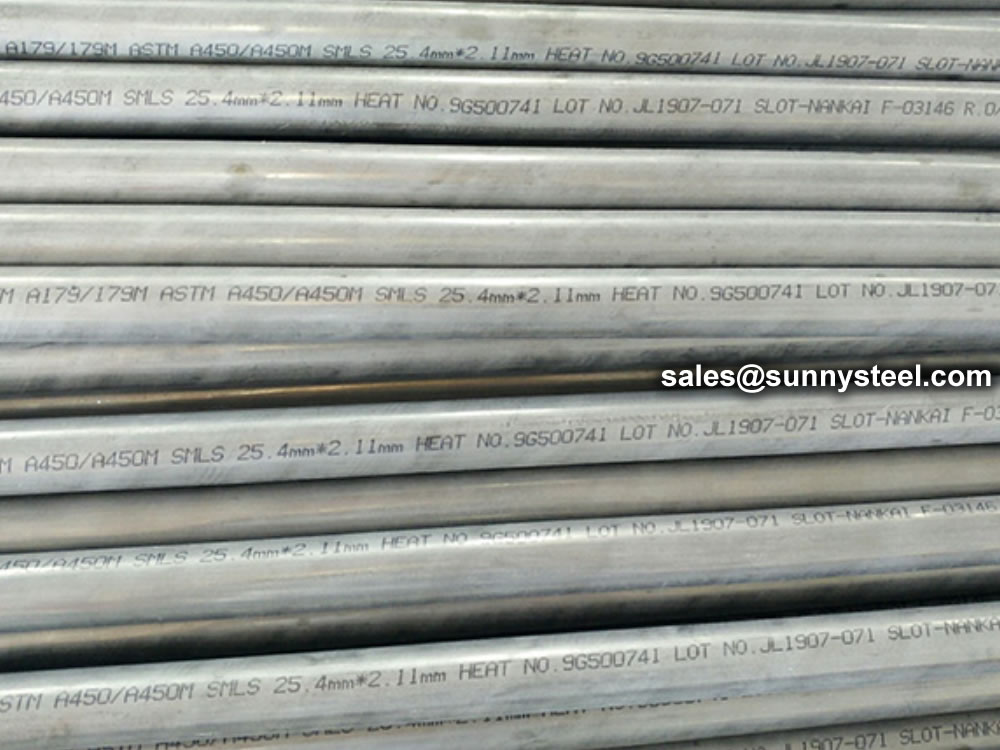
ASTM A450 is a standard specification for the general requirements of carbon and low alloy steel tubes.
Astm a450 pdf free downloadA450/A450M Standard Specification for General Requirements for Carbon and Low Alloy Steel Tubes.
The ASTM A450/A450M specification sets forth the general requirements that govern the production and testing of carbon and low alloy steel tubes. Its comprehensive scope covers aspects ranging from dimensions and tolerances to mechanical properties and tests, ensuring a cohesive and standardized approach to tube manufacturing.
The specification covers the following requirements:
ASTM A450 was published by ASTM International on November 1, 2021.
Also known as mild steel, low carbon steel has low strength relative to steel with higher carbon levels.
Carbon steel is broken down into four classes based on carbon content:
Dimensions and Tolerances: ASTM A450/A450M leaves no room for ambiguity when it comes to tube dimensions and tolerances. By providing strict guidelines for outside diameter, wall thickness, and length, it fosters uniformity across various applications.
Straightness and Finish: The standard's meticulous stipulations regarding tube straightness and surface finish contribute to the overall aesthetic and functional qualities of the tubes, ensuring they meet the rigorous demands of industrial applications.
Tensile and Hardness Tests: The ASTM A450/A450M specification mandates essential tests to evaluate the mechanical properties of the steel tubes. Tensile strength and hardness assessments provide insights into the tubes' ability to withstand external forces and pressures.
Flattening Test: By subjecting tubes to the flattening test, the standard ensures that tubes can endure the deformation caused by compression, a crucial consideration for applications involving pressure containment.
ASTM A450/A450M doesn't just address physical attributes; it embodies a philosophy of excellence. By delineating stringent requirements and test procedures, it safeguards the reliability and quality of carbon and low alloy steel tubes. This standard serves as a benchmark against which manufacturers and engineers can gauge their products, fostering confidence in their performance.
The influence of ASTM A450/A450M reverberates across a myriad of industries:
Construction: Structural integrity is paramount in construction. The standard's specifications ensure that steel tubes used in buildings, bridges, and other structures meet the highest quality standards.
Mechanical Engineering: In mechanical systems, precision and dependability are non-negotiable. ASTM A450/A450M-compliant tubes form the backbone of machines, mechanisms, and conveyance systems.
Energy and Utilities: From pipelines to heat exchangers, steel tubes play a pivotal role in energy production and distribution. The standard's provisions guarantee the safety and efficiency of these critical components.
In the intricate tapestry of industrial manufacturing, ASTM A450/A450M stands as a decisive thread, weaving together precision, reliability, and excellence. Its stipulations transcend the realm of specifications; they embody a commitment to quality that resonates across diverse applications. With ASTM A450/A450M, carbon and low alloy steel tubes find their compass, guiding them toward uncompromising standards of performance and integrity.
1.1 This specification В covers a group of requirements which, with the exceptions of 6.3 and Sections 7, 8, 19, 20, 21,22, 23, 24, and 25, are mandatory requirements to the following ASTM tubular product specifications:
| Title of Specification | ASTM Designation В A |
| Electric-Resistance-Welded Carbon Steel and Carbon Manganese Steel Boiler Tubes | A178/A178M |
| Seamless Cold-Drawn Low-Carbon Steel Heat-Exchanger and Condenser Tubes | A179/A179M |
| Seamless Carbon Steel Boiler Tubes for High-Pressure Service | A192/A192M |
| Seamless Medium-Carbon Steel Boiler and Super-heater Tubes | A210/A210M |
| Electric-Resistance-Welded Carbon Steel Heat-Exchanger and Condenser Tubes | A214/A214M |
| Seamless and Electric-Welded Low-Alloy Steel Tubes | A423/A423M |
| Specification for Seamless and Welded Carbon Steel Heat-Exchanger Tubes with Integral Fins | A498 |
| Seamless Cold-Drawn Carbon Steel Feedwater Heater Tubes | A556/A556M |
| Seamless, Cold-Drawn Carbon Steel Tubing for Hydraulic System Service | A822/A822M |
AВ These designations refer to the latest issue of the respective specifications.
В
1.2 One or more of Sections 6.3, 7, 8, 19, 20, 21, 22, 22.1,24, and 25 apply when the product specification or purchase order has a requirement for the test or analysis described by these sections.
1.3 In case of conflict between a requirement of the product specification and a requirement of this general requirement specification only the requirement of the product specification need be satisfied.
1.4 The values stated in either SI units or inch-pound units are to be regarded separately as standard. Within the text, the SI units are shown in brackets. The values stated in each system may not be exact equivalents; therefore, each system shall be used independently of the other. Combining values from the two systems may result in non-conformance with the standard. The inch-pound units shall apply unless the “M” designation (SI) of the product specification is specified in the order.
2.1 ASTM Standards:
A178/A178MВ Specification for Electric-Resistance-Welded Carbon Steel and Carbon-Manganese Steel Boiler and Superheater Tubes
A179/A179M Specification for Seamless Cold-Drawn Low-Carbon Steel Heat-Exchanger and Condenser Tubes
A192/A192M Specification for Seamless Carbon Steel Boiler Tubes for High-Pressure Service
A210/A210MВ Specification for Seamless Medium-Carbon Steel Boiler and Superheater Tubes
A214/A214M Specification for Electric-Resistance-Welded Carbon Steel Heat-Exchanger and Condenser Tubes
A370В Test Methods and Definitions for Mechanical Testing of Steel Products
A423/A423MВ Specification for Seamless and Electric-Welded Low-Alloy Steel Tubes
A498 Specification for Seamless and Welded Carbon Steel Heat-Exchanger Tubes with Integral Fins
A530/A530MВ Specification for General Requirements for Specialized Carbon and Alloy Steel Pipe
A556/A556MВ Specification for Seamless Cold-Drawn Carbon Steel Feedwater Heater Tubes
A700В Guide for Packaging, Marking, and Loading Methods for Steel Products for Shipment
A751 Test Methods, Practices, and Terminology for Chemical Analysis of Steel Products
A822/A822M Specification for Seamless Cold-Drawn Carbon Steel Tubing for Hydraulic System Service
A941 Terminology Relating to Steel, Stainless Steel, Related Alloys, and Ferroalloys
A1047/A1047M Test Method for Pneumatic Leak Testing of Tubing
A1058 Test Methods for Mechanical Testing of Steel ProductsвҖ”Metric
D3951 Practice for Commercial Packaging
E92 Test Method for Vickers Hardness of Metallic Materials (Withdrawn 2010) 5
E213 Practice for Ultrasonic Testing of Metal Pipe and Tubing
E273 Practice for Ultrasonic Testing of the Weld Zone of Welded Pipe and Tubing
E309 Practice for Eddy-Current Examination of Steel Tubular Products Using Magnetic Saturation
E426 Practice for Electromagnetic (Eddy-Current) Examination of Seamless and Welded Tubular Products, Titanium,Austenitic Stainless Steel and Similar Alloys
E570 Practice for Flux Leakage Examination of Ferromagnetic Steel Tubular Products
2.2 Federal Standard:
Fed. Std. No. 183 Continuous Identification Marking of Iron and Steel Products 6
2.3 Military Standards:
MIL-STD-163 Steel Mill Products Preparation for Shipment and Storage 6
MIL-STD-271 Nondestructive Testing Requirements for Metals 6
MIL-STD-792 Identification Marking Requirements for Special Purpose Equipment 6
2.4 ASME Boiler and Pressure Vessel Code:
Section IX 7
2.5 Steel Structures Painting Council:
SSPC-SP 6 Surface Preparation Specification No. 6 Commercial Blast Cleaning 8
2.6 Other Document:
SNT-TC-1A Recommended Practice for Nondestructive Personnel Qualification and Certification.
| Specified Outside Diameter | Specified Wall Thickness |
| 2 in. [50.8 mm] or less | 2 % or less of specified outside diameter |
| Greater than 2 in. [50.8mm] | 3 % or less of specified outside diameter |
| Any | 0.020 in. [0.5 mm] or less |
3.2 Other defined termsвҖ”The definitions in Test Methods and Definitions A370, Test Methods, Practices, and Terminology A751, and Terminology A941 are applicable to this specification and to those listed in 1.1.
4.1 It is the purchaser’s responsibility to specify in the purchase order all ordering information necessary to purchase the needed material. Examples of such information include, but are not limited to, the following:
4.1.1 Quantity (feet, metres, or number of lengths),
4.1.2 Specificiation number with grade or class, or both, as applicable and year date,
4.1.3 Manufacture (hot-finished or cold-finished),
4.1.4 Size (outside diameter and minimum wall thickness),
4.1.5 Length (specific or random),
4.1.6 Test report required (see Section 27),
4.1.7 Choice of testing track from the options listed in Test Methods A1058 when material is ordered to an M suffix (SI units) product standard. If the choice of test track is not specified in the order, then the defaultASTM test track shall be used as noted in Test Methods A1058.
4.1.8 Supplementary Requirements, and
4.1.9 Additional requirements.
5.1 The steel may be made by any process.
5.2 If a specific type of melting is required by the purchaser,it shall be as stated on the purchase order.
5.3 The primary melting may incorporate separate degassing or refining and may be followed by secondary melting,such as electroslag remelting or vacuum-arc remelting.
5.4 Steel may be cast in ingots or may be strand cast. When steel of different grades is sequentially strand cast, identification of the resultant transition material is required. The producer shall remove the transition material by an established procedure that positively separates the grades.
6.1 Samples for chemical analysis, and method of analysis shall be in accordance with Test Methods, Practices, and Terminology A751.
6.2 Heat AnalysisвҖ”If the heat analysis reported by the steel producer is not sufficiently complete for conformance with the heat analysis requirements of the applicable product specification to be fully assessed, the manufacturer may complete the assessment of conformance with such heat analysis requirements by using a product analysis for the specified elements that were not reported by the steel producer, provided that product analysis tolerances are not applied and the heat analysis is not altered.
6.3 Product AnalysisвҖ”Product analysis requirements and options, if any, are contained in the product specification.
7.1 The material shall conform to the requirements as to tensile properties prescribed in the individual specification.
7.2 The yield strength corresponding to a permanent offset of 0.2 % of the gage length or to a total extension of 0.5 % of the gage length under load shall be determined.
7.3 If the percentage of elongation of any test specimen is less than that specified and any part of the fracture is more than 3 вҒ?4 in. [19.0 mm] from the center of the gage length, as indicated by scribe marks on the specimen before testing, a retest shall be allowed.
8.1 The calculated weight per unit length, based upon a specified minimum wall thickness, shall be determined by the following equation:
W пјқC (D- t ) t В В В (1)
where:
C = 10.69 [0.0246615],
W = weight, lb/ft [kg/m],
D = specified outside diameter, in. [mm], and
t = specified minimum wall thickness, in. [mm]
8.2 The permissible variations from the calculated weight per foot [kilogram per metre] shall be as prescribed in Table 1.
TABLE 1 Permissible Variations in Weight Per Unit Length В A
| Method of Manufacture | Permissible Variation in Weight per Unit Length, % | |
| Over | Under | |
| Seamless, hot-finished | 16 | 0 |
| Seamless, cold-finished: | ||
| 1 1 вҒ?2 in. [38.1 mm] and under OD | 12 | 0 |
| Over 1 1 вҒ?2 in. [38.1 mm] OD | 13 | 0 |
| Welded | 10 | 0 |
AВ These permissible variations in weight apply to lots of 50 tubes or more in sizes 4 in. [101.6 mm] and under in outside diameter, and to lots of 20 tubes or more in sizes over 4 in. [101.6 mm] in outside diameter.
9.1 Variations from the specified minimum wall thickness shall not exceed the amounts prescribed in Table 2.
9.2 For tubes 2 in. [50.8 mm] and over in outside diameter and 0.220 in. [5.6 mm] and over in thickness, the variation in wall thickness in any one cross section of any one tube shall not exceed the following percentage of the actual mean wall at the section. The actual mean wall is defined as the average of the thickest and thinnest wall in that section.
Seamless tubes Вұ10 %
Welded tubes Вұ 5 %
9.3 When cold-finished tubes as ordered require wall thick-
nesses 3 вҒ?4 in. [19.1 mm] or over, or an inside diameter 60 % or less of the outside diameter, the permissible variations in wall thickness for hot-finished tubes shall apply.
TABLE 2 Permissible Variations in Wall Thickness В A
| Outside Diameter, in. [mm] |
Wall Thickness, % | |||||||
| 0.095[2.4] and Under | Over 0.095 to 0.150 [2.4 to 3.8], incl |
Over 0.150 to 0.180 [3.8 to 4.6], incl |
Over 0.180,[4.6] | |||||
| Over | Under | Over | Under | Over | Under | Over | Under | |
| Seamless, Hot-Finished Tubes | ||||||||
| 4 [101.6] and under | 40 | 0 | 35 | 0 | 33 | 0 | 28 | 0 |
| Over4 [101.6] | .... | .... | 35 | 0 | 33 | 0 | 28 | 0 |
| Seamless, Cold-Finished Tubes | ||||||||
| В | Over | Under | ||||||
| 1 1 вҒ?2 [38.1] and under | 20 | 0 | ||||||
| Over 1 1В вҒ?2 [38.1] | 22 | 0 | ||||||
| Welded Tubes | ||||||||
| All sizes | 18 | 0 | ||||||
AВ These permissible variations in wall thickness apply only to tubes, except internal-upset tubes, as rolled or cold-finished, and before swaging, expanding,bending, polishing, or other fabricating operations.
10.1 Except as provided in 10.2, variations from the specified outside diameter shall not exceed the amounts prescribed in Table 3.
10.2 Thin-wall tubes usually develop significant ovality (out of roundness) during final annealing, or straightening, or both.The diameter tolerances of Table 3 are not sufficient to provide for additional ovality expected in thin-wall tubes, and, for such tubes, are applicable only to the mean of the extreme (maximum and minimum) outside diameter readings in any one cross section. However, for thin wall tubes the difference in extreme outside diameter readings (ovality) in any one cross section shall not exceed the following ovality allowances:
| Outside Diameter | Ovality Allowance |
| 1 in. [25.4 mm] and under | 0.020 in. [0.5 mm] |
| Over 1 in. [25.4 mm] | 2.0 % of specified outside diameter |
TABLE 3 Permissible Variations in Outside DiameterВ A
| Outside Diameter,in. [mm] | Permissible Variations, in. [mm] | |
| Over | Under | |
| Hot-Finished Seamless Tubes | ||
| 4 [101.6] and under | 1 вҒ?64 [0.4] | 1 вҒ?32 [0.8] |
| Over 4 to 7 1 вҒ?2 [101.6 to 190.5], incl | 1 вҒ?64 [0.4] | 3 вҒ?64 [1.2] |
| Over 7 1 вҒ?2 to 9 [190.5 to 228.6], incl | 1 вҒ?64 [0.4] | 1 вҒ?16 [1.6] |
| Welded Tubes and Cold-Finished Seamless Tubes | ||
| Under 1 [25.4] | 0.004 [0.1] | 0.004 [0.1] |
| 1 to 1 1 вҒ?2 [25.4 to 38.1], incl | 0.006 [0.15] | 0.006 [0.15] |
| Over 1 1 вҒ?2 to 2 [38.1 to 50.8], excl | 0.008 [0.2] | 0.008 [0.2] |
| 2 to 2 1 вҒ?2 [50.8 to 63.5], excl | 0.010 [0.25] | 0.010 [0.25] |
| 2 1 вҒ?2 to 3 [63.5 to 76.2], excl | 0.012 [0.3] | 0.012 [0.3] |
| 3 to 4 [76.2 to 101.6], incl | 0.015 [0.38] | 0.015 [0.38] |
| Over 4 to 7 1 вҒ?2 [101.6 to 190.5], incl | 0.015 [0.38] | 0.025 [0.64] |
| Over 7 1 вҒ?2 to 9 [190.5 to 228.6], incl | 0.015 [0.38] | 0.045 [1.14] |
AВ Except as provided in 10.2, these permissible variations include out-of-roundness. These permissible variations in outside diameter apply to hot-finished seamless, welded and cold-finished seamless tubes before other fabricating operations such as upsetting, swaging, expanding, bending, or polishing.
11.1 Variations from the specified length shall not exceed the amounts prescribed in Table 4.
TABLE 4 Permissible Variations in LengthВ A
| Method of Manufacture |
Outside Diameter, in. [mm] |
Cut Length,in. [mm] | |
| Over | Under | ||
| Seamless, hot-finished | All sizes | 3 вҒ?16 [5] | 0 [0] |
| Seamless, cold-finished | Under 2 [50.8] | 1 вҒ?8 [3] | 0 [0] |
| 2 [50.8] and over | 3 вҒ?16 [5] | 0 [0] | |
| Welded | Under 2 [50.8] | 1 вҒ?8 [3] | 0 [0] |
| 2 [50.8] and over | 3 вҒ?16 [5] | 0 [0] | |
AВ These permissible variations in length apply to tubes before bending. They apply to cut lengths up to and including 24 ft [7.3 m]. For lengths greater than 24 ft [7.3m], the above over-tolerances shall be increased by 1 вҒ?8 in. [3 mm] for each 10 ft [3m] or fraction thereof over 24 ft or 1 вҒ?2 in. [13 mm], whichever is the lesser.
12.1 For tubes over 2 in. [50.8 mm] in outside diameter, or over 0.135 in. [3.44 mm] in wall thickness, the flash on the inside of the tubes shall be mechanically removed by cutting to a maximum height of 0.010 in. [0.25 mm] at any point on the tube.
12.2 For tubes 2 in. [50.8 mm] and under in outside diameter and 0.135 in. [3.4 mm] and under in wall thickness,the flash on the inside of the tube shall be mechanically removed by cutting to a maximum height of 0.006 in. [0.15mm] at any point on the tube.
13.1 Finished tubes shall be reasonably straight and have smooth ends free of burrs. They shall have a workmanlike finish. Surface imperfections (see Note 1) may be removed by grinding, provided that a smooth curved surface is maintained,and the wall thickness is not decreased to less than that permitted by this or the product specification. The outside diameter at the point of grinding may be reduced by the amount so removed.
N OTE 1вҖ”An imperfection is any discontinuity or irregularity found in the tube.
14.1 Repair welding of base metal defects in tubing is permissible only with the approval of the purchaser and with the further understanding that the tube shall be marked “WR” and the composition of the deposited filler metal shall be suitable for the composition being welded. Defects shall be thoroughly chipped or ground out before welding and each repaired length shall be reheat treated or stress relieved as required by the applicable specification. Each length of repaired tube shall be tested hydrostatically as required by the product specification.
14.2 Repair welding shall be performed using procedures and welders or welding operators that have been qualified in accordance with ASME Boiler and Pressure Vessel Code,Section IX.
15.1 If the results of the mechanical tests of any group or lot do not conform to the requirements specified in the individual specification, retests may be made on additional tubes of double the original number from the same group or lot, each of which shall conform to the requirements specified.
16.1 If the individual tubes or the tubes selected to represent any group or lot fail to conform to the test requirements, the individual tubes or the group or lot represented may be retreated and resubmitted for test. Not more than two reheat treatments shall be permitted.
17.1 Test specimens shall be taken from the ends of finished tubes prior to upsetting, swaging, expanding, or other forming operations, or being cut to length. They shall be smooth on the ends and free of burrs and flaws.
17.2 If any test specimen shows flaws or defective machining, it may be discarded and another specimen substituted.
18.1 The specimens and mechanical tests required shall be made in accordance with Annex A2 of Test Methods and Definitions A370 if inch-pound units are specified or to the requirements described in the applicable track of Test Methods A1058 if SI units are specified.
18.2 Specimens shall be tested at room temperature.
18.3 Small or subsize specimens as described in Test Methods and Definitions A370 or Test Methods A1058 may be used only when there is insufficient material to prepare one of the standard specimens. When using small or subsize specimens, the largest one possible shall be used.
19.1 A section of tube not less than 2 1 вҒ?2 in. [63 mm] in length for seamless and not less than 4 in. [100 mm] in length for welded shall be flattened cold between parallel plates in two steps. For welded tubes, the weld shall be placed 90В° from the direction of the applied force (at a point of maximum bending).During the first step, which is a test for ductility, no cracks or breaks, except as provided for in 19.4, on the inside, outside, or end surfaces shall occur in seamless tubes, or on the inside or outside surfaces of welded tubes, until the distance between the plates is less than the value of H calculated by the following equation:

where:
H = distance between flattening plates, in. [mm],
t = specified wall thickness of the tube, in. [mm],
D = specified outside diameter of the tube, in. [mm], and
e = deformation per unit length (constant for a given grade of steel: 0.07 for medium-carbon steel (maximum specified carbon 0.19 % or greater), 0.08 for low alloy steel, and 0.09 for low-carbon steel (maximum specified carbon 0.18 % or less)).
During the second step, which is a test for soundness, the flattening shall be continued until the specimen breaks or the opposite walls of the tube meet. Evidence of laminated or unsound material, or of incomplete weld that is revealed during the entire flattening test shall be cause for rejection.
19.2 Surface imperfections in the test specimens before flattening, but revealed during the first step of the flattening test, shall be judged in accordance with the finish requirements.
19.3 Superficial ruptures resulting from surface imperfections shall not be cause for rejection.
19.4 When low D-to-t ratio tubular products are tested,because the strain imposed due to geometry is unreasonably high on the inside surface at the six and twelve o’clock locations, cracks at these locations shall not be cause for rejection if the D to t ratio is less than 10.
20.1 A5 in. [100 mm] in length of finished welded tubing in sizes down to and including 1 вҒ?2 in. [12.7 mm] in outside diameter shall be split longitudinally 90В° on each side of the weld and the sample opened and flattened with the weld at the point of maximum bend. There shall be no evidence of cracks or lack of penetration or overlaps resulting from flash removal in the weld.
21.1 A section of tube approximately 4 in. [100 mm] in length shall stand being flared with a tool having a 60В° included angle until the tube at the mouth of the flare has been expanded to the percentages specified in Table 5 without cracking or showing imperfections rejectable under the provisions of the product specification.
TABLE 5 Flaring Test Requirements
| Ratio of Inside Diameter to Outside DiameterВ A |
Minimum Expansion of Inside Diameter, % |
|
| Carbon Steels | Low Alloy Steels | |
| 0.9 | 21 | 15 |
| 0.8 | 22 | 17 |
| 0.7 | 25 | 19 |
| 0.6 | 30 | 23 |
| 0.5 | 39 | 28 |
| 0.4 | 51 | 38 |
| 0.3 | 68 | 50 |
AВ In determining the ratio of inside diameter to specified outside diameter, the inside diameter shall be defined as the actual mean inside diameter of the material tested.
22.1 A section of tube shall be capable of having a flange turned over at a right angle to the body of the tube without cracking or showing imperfections rejectable under the provi-sions of the product specification. The width of the flange for carbon and alloy steels shall be not less than the percentages specified in Table 6.
TABLE 6 Flange Requirements
| Outside Diameter of Tube, in. [mm] | Width of Flange |
| To 2 1 вҒ?2 [63.5], incl | 15 % of OD |
| Over 2 1 вҒ?2 to 3 3 вҒ?4 [63.5 to 95.2], incl | 12 1 вҒ?2 % of OD |
| Over 3 3 вҒ?4 to 8 [95.2 to 203.2], incl | 10 % of OD |
23.1 For tubes 0.200 in. [5.1 mm] and over in wall thickness, either the Brinell or Rockwell hardness test shall be used. When Brinell hardness testing is used, a 10-mm ball with 3000, 1500, or 500-kg load, or a 5-mm ball with 750-kg load may be used, at the option of the manufacturer.
23.2 For tubes less than 0.200 in. [5.1 mm] to and including 0.065 in. [1.7 mm] in wall thickness, the Rockwell hardness test shall be used.
23.3 For tubes less than 0.065 in. [1.7 mm] in wall thickness, the hardness test shall not be required.
23.4 The Brinell hardness test may be made on the outside of the tube near the end, on the outside of a specimen cut from the tube, or on the wall cross section of a specimen cut from the tube at the option of the manufacturer. This test shall be made so that the distance from the center of the impression to the edge of the specimen is at least 2.5 times the diameter of the impression.
23.5 The Rockwell hardness test may be made on the inside surface, on the wall cross section, or on a flat on the outside surface at the option of the manufacturer.
23.6 For tubes furnished with upset, swaged, or otherwise formed ends, the hardness test shall be made as prescribed in
23.1 and 23.2 on the outside of the tube near the end after the forming operation and heat treatment.
23.7 For welded or brazed tubes, the hardness test shall be made away from the joints.
23.8 When the product specification provides for Vickers hardness, such testing shall be in accordance with Test Method E92.
24.1 Except as provided in 24.2 and 24.3, each tube shall be tested by the manufacturer to a minimum hydrostatic test pressure determined by the following equation:
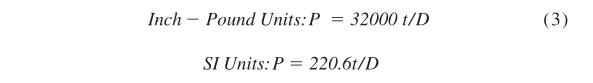
where:
P = hydrostatic test pressure, psi or MPa,
t = specified wall thickness, in. or mm, and
D = specified outside diameter, in. or mm.
24.1.1 The hydrostatic test pressure determined by Eq 3 shall be rounded to the nearest 50 psi [0.5 MPa] for pressure below 1000 psi [7 MPa], and to the nearest 100 psi [1 MPa] for pressures 1000 psi [7 MPa] and above. The hydrostatic test may be performed prior to cutting to final length, or prior to upsetting, swaging, expanding, bending or other forming operations, or both.
24.2 Regardless of the determination made by Eq 3, the minimum hydrostatic test pressure required to satisfy these requirements need not exceed the values given in Table 7. This does not prohibit testing at higher pressures at manufacturer’s option or as provided in 24.3.
TABLE 7 Hydrostatic Test Pressures
| Outside Diameter of Tube, in. [mm] | Hydrostatic Test Pressure, psi [MPa] |
| Under 1 [25.4] | 1000 [7] |
| 1 to 1 1 вҒ?2 [25.4 to 38.1], excl | 1500 [10] |
| 1 1 вҒ?2 to 2 [38.1 to 50.8], excl | 2000 [14] |
| 2 to 3 [50.8 to 76.2], excl | 2500 [17] |
| 3 to 5 [76.2 to 127], excl | 3500 [24] |
| 5 [127] and over | 4500 [31] |
24.3 With concurrence of the manufacturer, a minimum hydrostatic test pressure in excess of the requirements of 24.2 or 24.1, or both, may be stated on the order. The tube wall stress shall be determined by the following equation:

where:
S = tube wall stress, psi or MPa, and all other symbols as
defined in 24.1.1.
24.4 The test pressure shall be held for a minimum of 5 s.
24.5 If any tube shows leaks during the hydrostatic test, it shall be rejected.
24.6 The hydrostatic test may not be capable of testing the end portion of the pipe. The lengths of pipe that cannot be tested shall be determined by the manufacturer and, when specified in the purchase order, reported to the purchaser.
25.1 Air Underwater TestвҖ”When this test is employed,each tube, with internal surface clean and dry, shall be internally pressurized to 150 psi [1000 kPa] minimum with clean and dry compressed air while being submerged in clear water. The tube shall be well-lighted, preferably by underwater illumination. Any evidence of air leakage of the pneumatic couplings shall be corrected prior to testing. Inspection shall be made of the entire external surface of the tube after holding the pressure for not less than 5 s after the surface of the water has become calm. If any tube shows leakage during the air underwater test, it shall be rejected. Any leaking areas may be cut out and the tube retested.
25.2 Pneumatic Leak TestвҖ”When this test is employed,each tube shall be subjected to a pneumatic leak test in accordance with Specification A1047/A1047M.
Acceptance criteria shall be as follows:
| Tube O.D. in [mm] | Calibration Hole, max. in [mm] |
| вү?.5 [вү?0] | 0.003 [0.076] |
| >1.5вү?.0 [>40вү?0] | 0.004 [0.162] |
| >2.0вү?.5 [>50вү?5] | 0.005 [0.127] |
| >2.5вү?.0 [>65вү?5] | 0.006 [0.152] |
| >3.0 [>75] | by agreement |
26.1 When nondestructive examination is specified by the purchaser or the product specification, each tube shall be examined by a nondestructive examination method in accordance with Practice E213, Practice E309 (for ferromagnetic materials), Practice E426 (for non-magnetic materials), or Practice E570. Upon agreement, Practice E273 shall be employed in addition to one of the full periphery tests. The range of tube sizes that may be examined by each method shall be subject to the limitations in the scope of that practice. In case of conflict between these methods and practices and this specification, the requirements of this specification shall prevail.
26.2 The following information is for the benefit of the user of this specification.
26.2.1 Calibration standards for the nondestructive electric test are convenient standards for calibration of nondestructive testing equipment only. For several reasons, including shape, orientation, width, etc., the correlation between the signal produced in the electric test from an imperfection and from calibration standards is only approximate. A purchaser interested in ascertaining the nature (type, size, location, and orientation) of discontinuities that can be detected in the specific application of these examinations should discuss this
with the manufacturer of the tubular product.
26.2.2 The ultrasonic examination referred to in this specification is intended to detect longitudinal discontinuities having a reflective area similar to or larger than the calibration reference notches specified in 26.4. The examination may not detect circumferentially oriented imperfections or short, deep defects.
26.2.3 The eddy current examination referenced in this specification has the capability of detecting significant discontinuities, especially of the short abrupt type. Practices E309 and E426 contain additional information regarding the capabilities and limitations of eddy-current examination.
26.2.4 The flux leakage examination referred to in this specification is capable of detecting the presence and location of significant longitudinally or transversely oriented discontinuities. The provisions of this specification only provide for longitudinal calibration for flux leakage. It should be recognized that different techniques should be employed to detect differently oriented imperfections.
26.2.5 The hydrostatic test referred to in Section 23 is a test method provided for in many product specifications. This test has the capability of finding defects of a size permitting the test fluid to leak through the tube wall and may be either visually seen or detected by a loss of pressure. This test may not detect very tight, through-the-wall defects or defects that extend an appreciable distance into the wall without complete penetration.
26.2.6 A purchaser interested in ascertaining the nature(type, size, location, and orientation) of discontinuities that can be detected in the specific application of these examinations should discuss this with the manufacturer of the tubular products.
26.3 Time of ExaminationвҖ”Nondestructive examination for specification acceptance shall be performed after all deformation processing, heat treating, welding, and straightening operations. This requirement does not preclude additional testing at earlier stages in the processing.
26.4 Surface Condition:
26.4.1 All surfaces shall be free of scale, dirt, grease, paint,or other foreign material that could interfere with interpretation of test results. The methods used for cleaning and preparing the surfaces for examination shall not be detrimental to the base metal or the surface finish.
26.4.2 Excessive surface roughness or deep scratches can produce signals that interfere with the test.
26.5 Extent of Examination:
26.5.1 The relative motion of the tube and the transducer(s),coil(s), or sensor(s) shall be such that the entire tube surface is scanned, except for end effects as noted in 26.5.2.
26.5.2 The existence of end effects is recognized, and the extent of such effects shall be determined by the manufacturer,and, if requested, shall be reported to the purchaser. Other nondestructive tests may be applied to the end areas, subject to agreement between the purchaser and the manufacturer.
26.6 Operator Qualifications:
26.6.1 The test unit operator shall be certified in accordance with SNT-TC-1A, or an equivalent documented standard agreeable to both purchaser and manufacturer.
26.7 Test Conditions:
26.7.1 For examination by the ultrasonic method, the minimum nominal transducer frequency shall be 2.0 MHz, and the maximum transducer size shall be 1.5 in. [38 mm].
26.7.2 For eddy current testing, the excitation coil frequency shall be chosen to ensure adequate penetration, yet provide good signal-to-noise ratio.
26.7.2.1 The maximum coil frequency shall be:
| Specified Wall Thickness | Maximum Frequency |
| <0.050 in. | 100 KHz |
| 0.050 to 0.150 | 50 |
| >0.150 | 10 |
26.8 Reference Standards:
26.8.1 Reference standards of convenient length shall be prepared from a length of tube of the same grade, specified size (outside diameter and wall thickness), surface finish and heat treatment condition as the tubing to be examined.
26.8.2 For eddy current testing, the reference standard shall contain, at the option of the manufacturer, any one of the following discontinuities:
26.8.2.1 Drilled HoleвҖ”The reference standard shall contain three or more holes, equally spaced circumferentially around the tube and longitudinally separated by a sufficient distance to allow distinct identification of the signal from each hole. The holes shall be drilled radially and completely through the tube wall, with care being taken to avoid distortion of the tube while drilling. The holes shall not be larger than 0.031 in. [0.8 mm] in diameter.As an alternative, the producer may choose to drill one hole and run the calibration standard through the test coil three times, rotating the tube approximately 120В° each time.More passes with smaller angular increments may be used,provided testing of the full 360В° of the coil is obtained. For welded tubing, if the weld is visible, one of the multiple holes or the single hole shall be drilled in the weld.
26.8.2.2 Transverse Tangential NotchвҖ”Using a round tool or file with a 1 вҒ?4 in. [6.4 mm] diameter, a notch shall be milled or filed tangential to the surface and transverse to the longitudinal axis of the tube. Said notch shall have a depth not exceeding 12 1 вҒ?2 % of the specified wall thickness of the tube or 0.004 in. [0.1 mm], whichever is greater.
26.8.2.3 Longitudinal NotchвҖ”Anotch 0.031 in. [0.8 mm] or less in width shall be machined in a radial plane parallel to the tube axis on the outside surface of the tube, to have a depth not exceeding 12 1 вҒ?2 % of the specified wall thickness of the tube or 0.004 in. [0.1 mm], whichever is greater. The length of the notch shall be compatible with the testing method.
26.8.3 For ultrasonic testing, the reference ID and OD notches shall be any one of the three common notch shapes shown in Practice E213, at the option of the manufacturer. The depth of the notches shall not exceed 12 1 вҒ?2 % of the specified wall thickness of the tube or 0.004 in. [0.1 mm], whichever is greater. The width of the notch shall not exceed two times the depth. For welded tubing, the notches shall be placed in the weld, if the weld is visible.
26.8.4 For flux leakage testing, the longitudinal reference notches shall be straight-sided notches machined in a radial plane parallel to the tube axis on the inside and outside surfaces of the tube. Notch depth shall not exceed 12 1 вҒ?2 % of the specified wall thickness or 0.004 in. [0.1 mm], whichever is greater. Notch length shall not exceed 1 in. [25.4 mm], and the width shall not exceed the depth. Outside and inside notches shall have sufficient separation to allow distinct identification of the signal from each notch.
26.8.5 More or smaller reference discontinuities, or both,may be used by agreement between the purchaser and the manufacturer.
26.9 Standardization Procedure:
26.9.1 The test apparatus shall be standardized at the beginning and end of each series of tubes of the same specified size (diameter and wall thickness), grade and heat treatment condition, and at intervals not exceeding 4 h during the examination of such tubing. More frequent standardizations may be performed at the manufacturer’s option or may be required upon agreement between the purchaser and the manufacturer.
26.9.2 The test apparatus shall also be standardized after any change in test system settings, change of operator, equipment repair, or interruption due to power loss or shutdown.
26.9.3 The reference standard shall be passed through the test apparatus at the same speed and test system settings as the tube to be tested, except that, at the manufacturer’s discretion,the tubes may be tested at a higher sensitivity.
26.9.4 The signal-to-noise ratio for the reference standard shall be 2.5:1 or greater, and the reference signal amplitude for each discontinuity shall be at least 50 % of full scale of the display. In establishing the noise level, extraneous signals fromidentifiable surface imperfections on the reference standard may be ignored. When reject filtering is used during UT testing, linearity must be demonstrated.
26.9.5 If, upon any standardization, the reference signal amplitude has decreased by 29 % (3.0 dB), the test apparatus shall be considered out of standardization. The test system settings may be changed, or the transducer(s), coil(s), or sensor(s) adjusted, and the unit restandardized, but all tubes tested since the last acceptable standardization must be retested.
26.10 Evaluation of Imperfections:
26.10.1 Tubing producing a test signal to or greater than the lowest signal produced by the reference standard shall be designated suspect, shall be clearly marked or identified, and shall be separated from the acceptable tubing.
26.10.2 Such suspect tubing shall be subject to one of the following three dispositions:
26.10.2.1 The tubes may be rejected without further examination, at the discretion of the manufacturer.
26.10.2.2 If the test signal was produced by imperfections such as scratches, surface roughness, dings, straightener marks,loose ID bead and cutting chips, steel die stamps, stop marks,tube reducer ripple, or chattered flash trim, the tubing may be accepted or rejected depending on visual observation of the severity of the imperfection, the type of signal it produces on the testing equipment used, or both.
26.10.2.3 If the test signal was produced by imperfections which cannot be identified, or was produced by cracks or crack-like imperfections, the tubing shall be rejected.
26.10.3 Any tubes with imperfections of the types in 26.10.2.2 and 26.10.2.3, exceeding 0.004 in. [0.1 mm] or 12 1 вҒ?2 % of the specified minimum wall thickness (whichever is greater) in depth shall be rejected.
26.10.4 Rejected tubes may be reconditioned and retested providing the wall thickness is not decreased to less than that required by this or the product specification. If grinding is performed, the outside diameter in the area of grinding may be reduced by the amount so removed. To be accepted, reconditioned tubes must pass the nondestructive examination by which they were originally rejected.
27.1 When specified in the purchase order or contract, the producer or supplier shall furnish a test report stating that the material was manufactured, sampled, tested and inspected in accordance with the specification, including year date, the supplementary requirements, and any other requirements designated in the purchase order or contract, and that the results met the requirements of that specification, the supplementary requirements and the other requirements. A signature or notarization is not required on the test report, but the document shall be dated and shall clearly identify the organization submitting the report. Notwithstanding the absence of a signature or notarization, the organization submitting the report is responsible for the contents of the report.
27.2 In addition, the test report shall include the following information and test results, when applicable:
27.2.1 Heat Number,
27.2.2 Heat Analysis,
27.2.3 Product Analysis, when specified,
27.2.4 Tensile Properties,
27.2.5 Width of the gage length, when longitudinal strip tension test specimens are used,
27.2.6 Flattening Test acceptable,
27.2.7 Reverse Flattening Test acceptable,
27.2.8 Flaring Test acceptable,
27.2.9 Flange Test acceptable,
27.2.10 Hardness Test values,
27.2.11 Hydrostatic Test pressure,
27.2.12 Non-destructive Electric Test method,
27.2.13 Impact Test results, and
27.2.14 Other test results or information required to be reported by the product specification.
27.3 Test results or information required to be reported by supplementary requirements, or other requirements designated in the purchase order or contract shall be reported, but may be reported in a separate document.
27.4 The test report shall include a statement of explanation for the letter added to the specification number marked on the tubes (see 30.2), when all of the requirements of the specification have not been completed. The purchaser must certify that all requirements of the specification have been completed before removal of the letter (that is, X, Y, or Z).
27.5 A test report, certificate of compliance, or similar document printed from or used in electronic form from an electronic data interchange (EDI) transmission shall be regarded as having the same validity as a counterpart printed in the certifier’s facility. The content of the EDI transmitted document shall meet the requirements of the invoked ASTM standard(s) and conform to any existing EDI agreement between the purchaser and supplier. Notwithstanding the absence of a signature, the organization submitting the EDI transmission is responsible for the content of the report.
28. Inspection
28.1 The inspector representing the purchaser shall have entry at all times while work on the contract of the purchaser is being performed, to all parts of the manufacturer’s works that concern the manufacture of the material ordered. The manufacturer shall afford the inspector all reasonable facilities to satisfy him that the material is being furnished in accordance with this specification. All required tests and inspection shall be made at the place of manufacture prior to shipment, unless otherwise specified, and shall be conducted so as not to interfere unnecessarily with the operation of the works.
29.1 Each length of tubing received from the manufacturer may be inspected by the purchaser and, if it does not meet the requirements of the specification based on the inspection and test method as outlined in the specification, the length may be rejected and the manufacturer shall be notified. Disposition of rejected tubing shall be a matter of agreement between the manufacturer and the purchaser.
29.2 Material that fails in any of the forming operations or in the process of installation and is found to be defective shall be set aside and the manufacturer shall be notified for mutual evaluation of the material’s suitability. Disposition of such material shall be a matter for agreement.
30.1 Each length of tube shall be legibly stenciled with the manufacturers’s name or brand, the specification number, and grade. The marking need not include the year date of the specification. For tubes less than 1 1 вҒ?4 in. [31.8 mm] in diameter and tubes under 3 ft. [1 m] in length, the required information may be marked on a tag securely attached to the bundle or box in which the tubes are shipped.
30.2 When it is specified that certain requirements of a specification adopted by the ASME Boiler and Pressure Vessel Committee are to be completed by the purchaser upon receipt of the material, the manufacturer shall indicate that all requirements of the specification have not been completed by a letter such as X, Y, or Z, immediately following the specification number. This letter may be removed after completion of all requirements in accordance with the specification. An explanation of specification requirements to be completed is pro-
vided in Section 27.
30.3 Bar CodingвҖ”In addition to the requirements in 30.1 and 30.2, bar coding is acceptable as a supplemental identification method. The purchaser may specifiy in the order a specific bar coding system to be used.
31.1 When specified on the purchase order, packaging,marking, and loading for shipment shall be in accordance with the procedures of Practices A700.
32.1 Scale Free Pipe:
32.1.1 When specified in the contract or order, the following requirements shall be considered in the inquiry contract or order, for agencies of the U.S. Government where scale free tube is required. These requirements shall take precedence if there is a conflict between these requirements and the product specification.
32.1.2 Tube shall be ordered to outside diameter (OD) and wall thickness.
32.1.3 Responsibility for InspectionвҖ”Unless otherwise specified in the contract or purchase order, the manufacturer is responsible for the performance of all inspection and test requirements specified. The absence of any inspection requirements in the specification shall not relieve the contractor of the responsibility for ensuring that all products or supplies submitted to the Government for acceptance comply with all requirements of the contract. Sampling inspection, as part of the manufacturing operations, is an acceptable practice to ascertain conformance to requirements, however, this does not authorize submission of known defective material, either indicated or actual, nor does it commit the Government to accept the material. Except as otherwise specified in the contract or purchase order, the manufacturer may use his own or any other suitable facilities for the performance of the inspection and test requirements unless disapproved by the purchaser at the time the order is placed. The purchaser shall have the right to perform any of the inspections and tests set forth when such inspections and tests are deemed necessary to ensure that the material conforms to the prescribed requirements.
32.1.4 Sampling for Flattening and Flaring Test and for Visual and Dimensional ExaminationвҖ”Minimum sampling for flattening and flaring tests and visual and dimensional examination shall be as follows:
| Lot Size (pieces per lot) | Sample Size |
| 2 to 8 | Entire lot |
| 9 to 90 | 8 |
| 91 to 150 | 12 |
| 151 to 280 | 19 |
| 281 to 500 | 21 |
| 501 to 1200 | 27 |
| 1201 to 3200 | 35 |
| 3201 to 10 000 | 38 |
| 10 001 to 35 000 | 46 |
In all cases, the acceptance number is zero and the rejection number is one. Rejected lots may be screened and resubmitted for visual and dimensional examination. All defective items shall be replaced with acceptable items prior to lot acceptance
32.1.5 Sampling for Chemical AnalysisвҖ”One sample for chemical analysis shall be selected from each of two tubes chosen from each lot. A lot shall be all material poured from one heat.
32.1.6 Sampling for Tension and Bend TestвҖ”One sample shall be taken from each lot.Alot shall consist of all tube of the same outside diameter and wall thickness manufactured during an 8-h shift from the same heat of steel, and heat treated under the same conditions of temperature and time in a single charge in a batch type furnace, or heat treated under the same condition in a continuous furnace, and presented for inspection at the same time.
32.1.7 Hydrostatic and Ultrasonic TestsвҖ”Each tube shall be tested by the ultrasonic (when specified) and hydrostatic tests.
32.1.8 Tube shall be free from heavy oxide or scale. The internal surface of hot finished ferritic steel tube shall be pickled or blast cleaned to a free of scale condition equivalent to the CSa2 visual standard listed in SSPC-SP6. Cleaning shall be performed in accordance with a written procedure that has been shown to be effective. This procedure shall be available for audit.
32.1.9 In addition to the marking in Specification A530/A530M, each length of tube 1 вҒ?4 in. outside diameter and larger shall be marked with the following listed information. Marking shall be in accordance with Fed. Std. No. 183 and MIL-STD-792. (a) Outside diameter, wall thickness, and length (b) Heat or lot identification number.
32.1.10 Tube shall be straight to within the tolerances specified in Table 8:
TABLEВ 8 Straightness Tolerances
| Specified OD (in.) | Specified Wall Thickness (in.) |
Maximum Curvature in Any 3 ft (in.) | Maximum Curvature in Total Length (in.) |
| Up to 5.0, incl | Over 3 % OD to 0.5, incl |
0.030 | 0.010 Г— length, ft |
| Over 5.0 to 8.0,incl. | Over 4 % OD to 0.75,incl | 0.045 | 0.015 Г— length, ft |
| Over 8.0 to 12.75,incl. | Over 4 % OD to 1.0, incl |
0.060 | 0.020 Г— length, ft |
32.1.11 When specified, each tube shall be ultrasonically examined in accordance with MIL-STD-271, except that the notch depth in the calibration standard shall be 5 % of the wall thickness or 0.005 in., whichever is greater. Any tube which produces an indication equal to or greater than 100 % of the indication from the calibration standard shall be rejected.
32.1.12 The tube shall be free from repair welds, welded joints, laps, laminations, seams, visible cracks, tears, grooves,slivers, pits, and other imperfections detrimental to the tube as determined by visual and ultrasonic examination, or alternate tests, as specified.
32.1.13 Tube shall be uniform in quality and condition and have a finish conforming to the best practice for standard quality tubing. Surface imperfections such as handling marks,straightening marks, light mandrel and die marks, shallow pits,and scale pattern will not be considered injurious if the imperfections are removable within the tolerances specified for wall thickness or 0.005 in., whichever is greater. The bottom of imperfections shall be visible and the profile shall be rounded and faired-in.
32.1.14 No weld repair by the manufacturer is permitted.
32.1.15 Preservation shall be level A or commercial, and packing shall be level A, B, or commercial, as specified. Level A preservation and level A or B packing shall be in accordance with MIL-STD-163 and commercial preservation and packing shall be in accordance with Practices A700 or Practice D3951.
33.1 alloy steel tube; austenitic stainless steel; carbon steel tube; general delivery; stainless steel tube; steel tube
ASTM A29 is a standard specification for carbon and alloy steel bars. The specification covers general requirements for hot-wrought steel bars. The specification includes hot rolled carbon steel bars, cold finished carbon steel bars, hot rolled alloy steel bars, and cold finished alloy steel bars.
ASTM A29 specifies a minimum yield strength of 40,000 to 105,000 psi. ASTM A29 and A36 have similar carbon content levels, but different mechanical properties. ASTM A36 is designed for structural applications and has a minimum yield strength of 36,000 psi.
ASTM A29 sets standards for the chemical composition, mechanical properties, and heat treatment of the steel. For example, ASTM A29 4140 alloy steel is usually supplied ready heat treated to hardness in 18-22 HRC.
Medium-carbon steel is used to make shafts, axles, gears, crankshafts, couplings, and forgings. This type of steel has a carbon content of 0.30% to 0.60% and a manganese content of 0.60% to 1.65%.
Medium-carbon steel is stronger than low-carbon steel, but it's less ductile and tough. After fabrication, it can be heat-treated.
Medium-carbon steel is also used for:
Other types of carbon steel include:
Carbon steel is classified into four types based on its carbon content:
The hardness of the steel increases as the percentage of carbon increases. Each type of carbon steel has unique properties that make it suitable for different applications. For example, low-carbon steel is the most common type of carbon steel and is used for automotive components. High-carbon steel is the strongest but most brittle type of carbon steel.

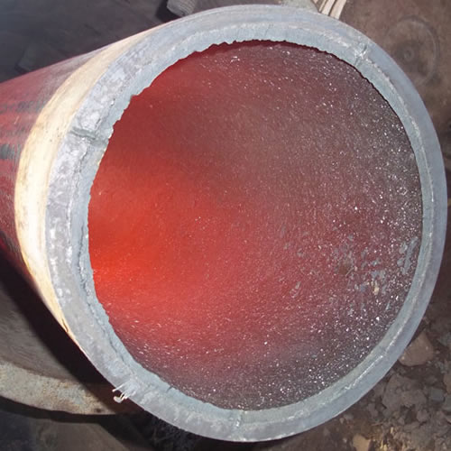
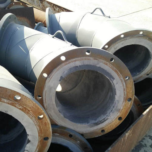
Ceramic lined pipe is made through self-propagating high-temperature synthesis (SHS) technique.
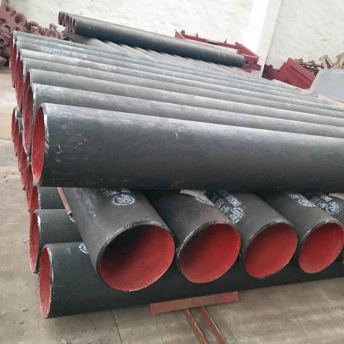
Cast basalt lined steel pipe is composed by lined with cast basalt pipe, outside steel pipe and cement mortar filling between the two layers.
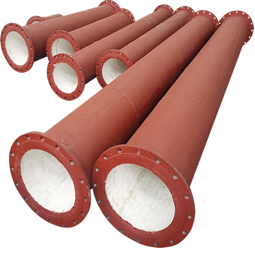
Ceramic tile lined pipes have very uniform coating of specially formulated ceramic material that is affixed to the inner of the pipe.
The material of the rare earth alloy wear-resistant pipe is ZG40CrMnMoNiSiRe, which is also the grade of rare earth alloy steel.
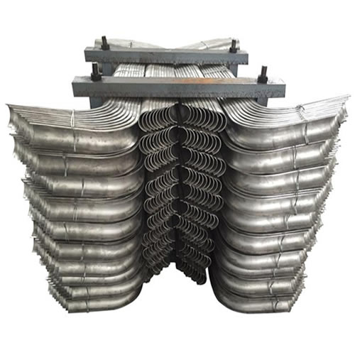
Tubes Erosion Shields are used to protect boiler tubing from the highly erosive effects of high temperatures and pressures thereby greatly extending tube life.
The ASTM A213 T91 seamless tubes are primarily used for boiler, superheater, and heat-exchanger.

When you partner with Sunny Steel, you can stop worrying about meeting deadlines thanks to our responsive and timely service. You'll also say goodbye to unnecessary shopping around. Instead, you'll get white glove service from an expert who understands your needs and can get you the materials you need quickly.