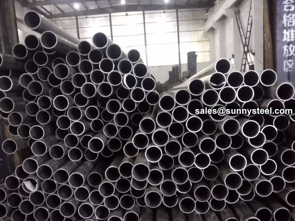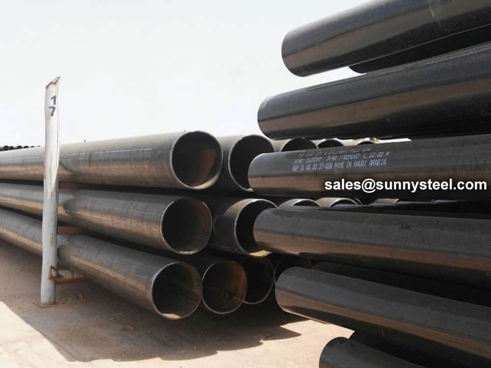
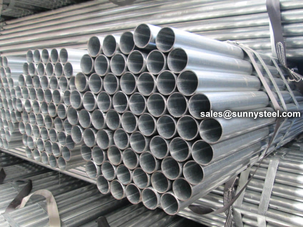
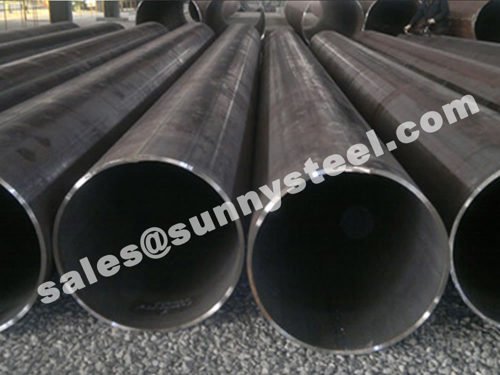
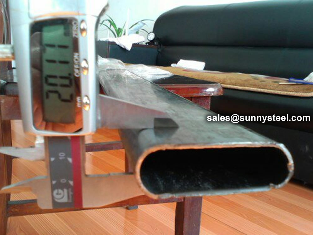
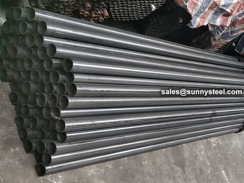
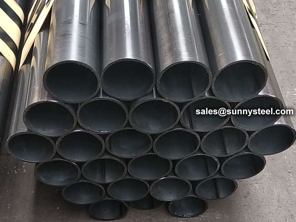
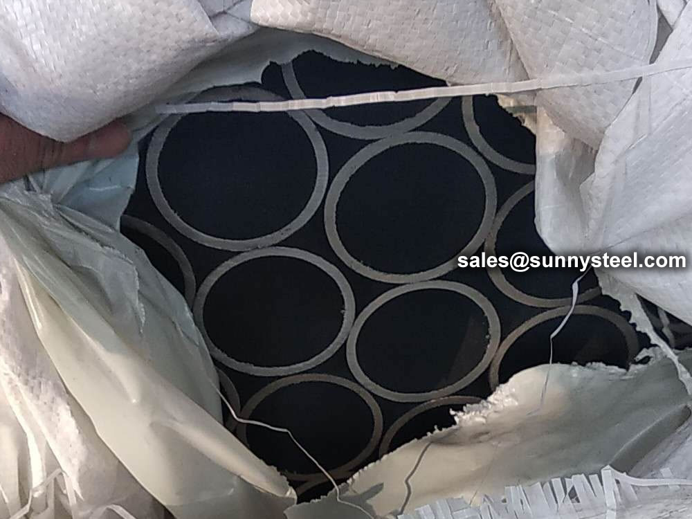
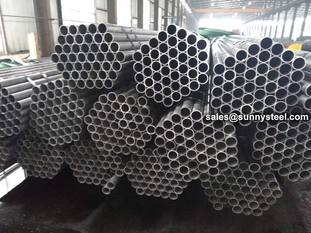
ERW Galvanized Steel Pipe
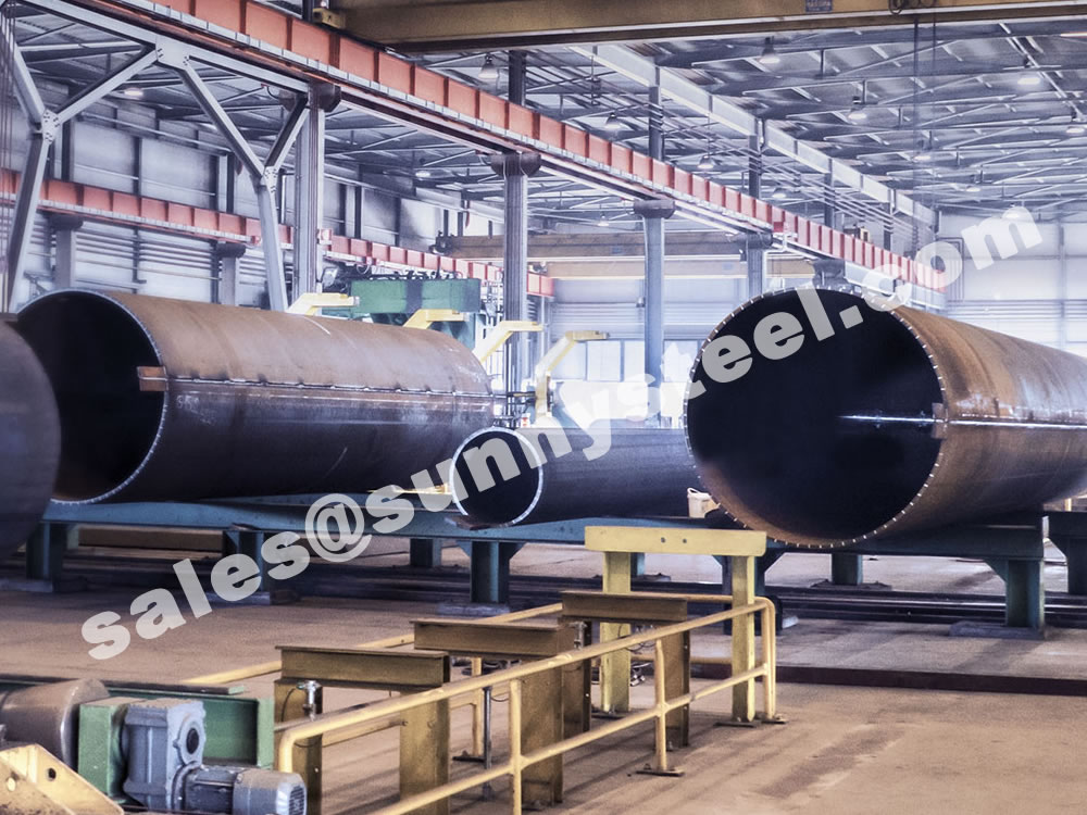
ERW Galvanized Steel Pipe - industrial steel pipe
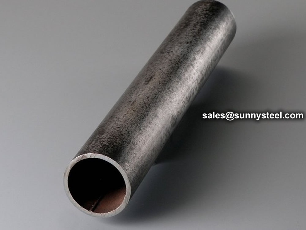
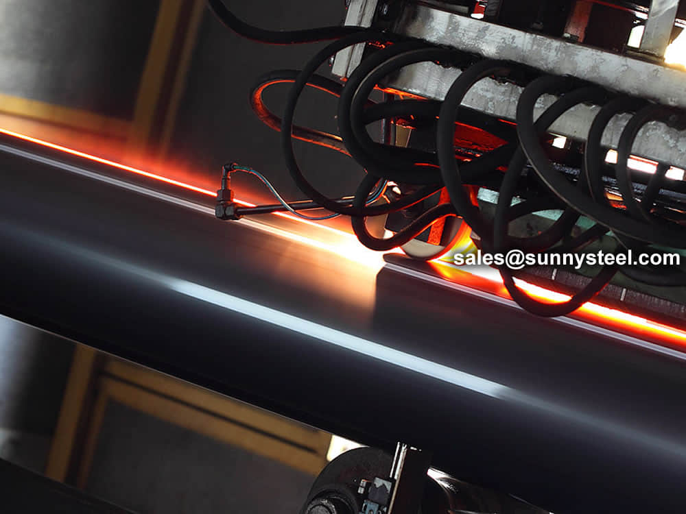
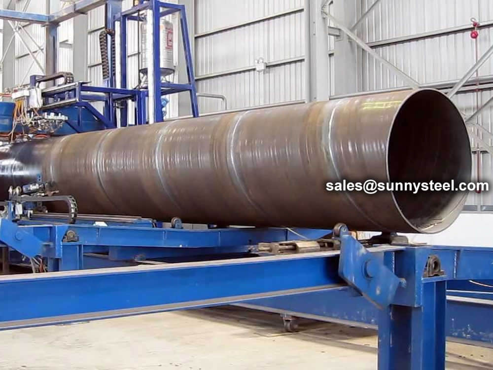
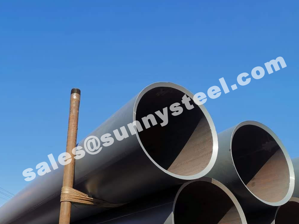
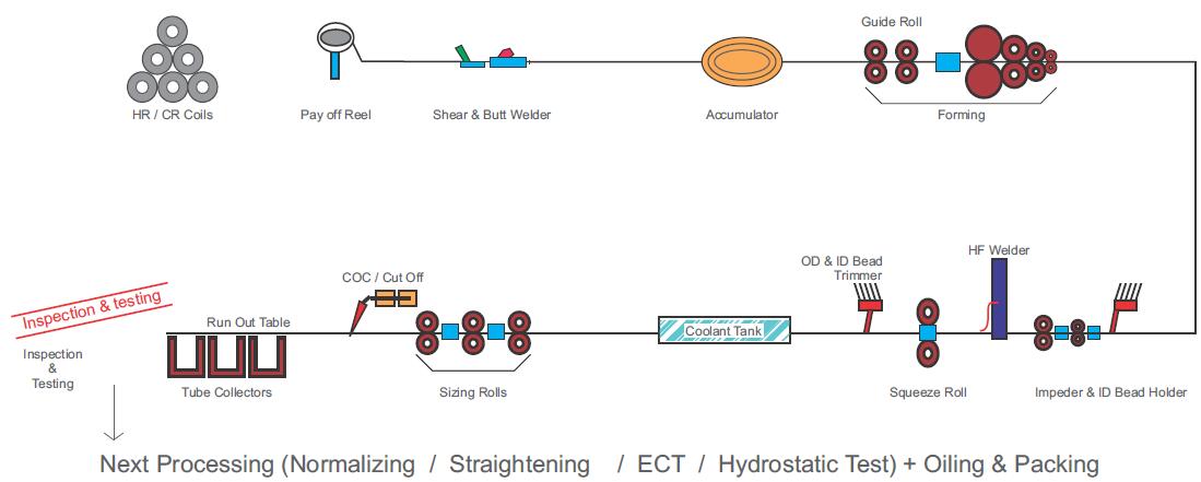
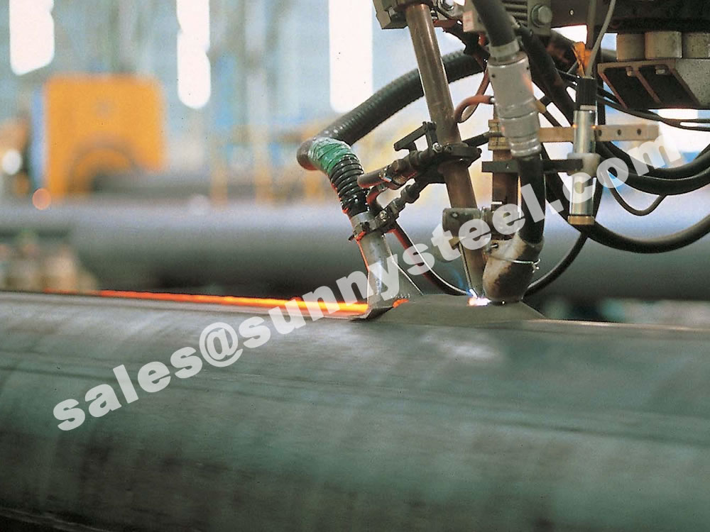
ERW (Electric Resistance Welded) steel pipe is formed by rolling steel coils into a tube and connecting the extremities using two copper electrodes.
These electrodes, which are disc-shaped and rotate as the material passes between them, stay in constant contact to create long continuous welds. Advances in welding technology continue to enhance the process.
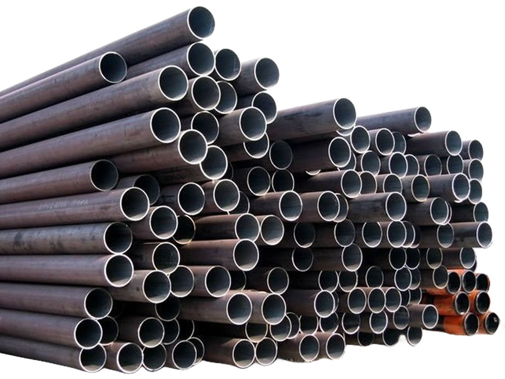
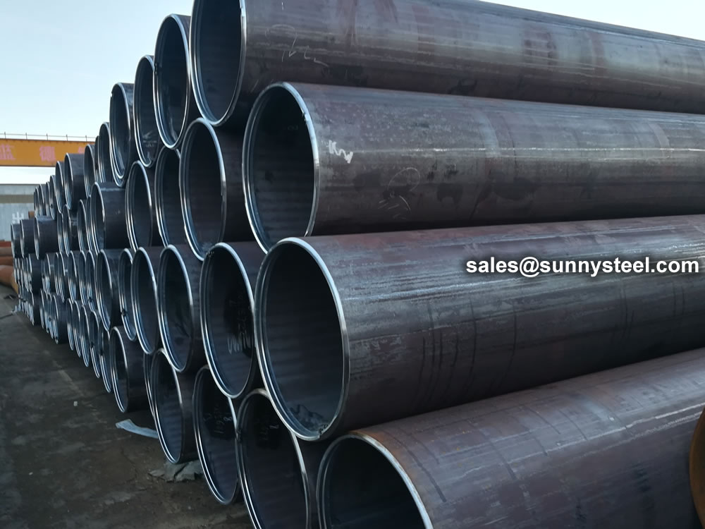
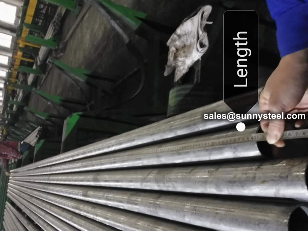
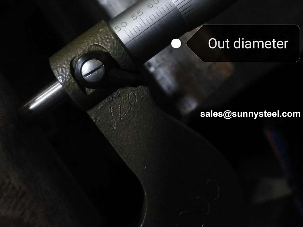
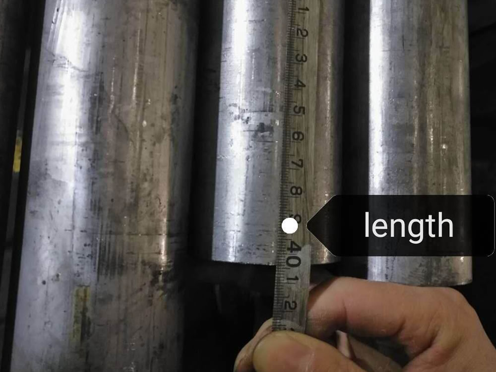
Diameter: ½ inches (15mm) to 24 inches (21.34mm).
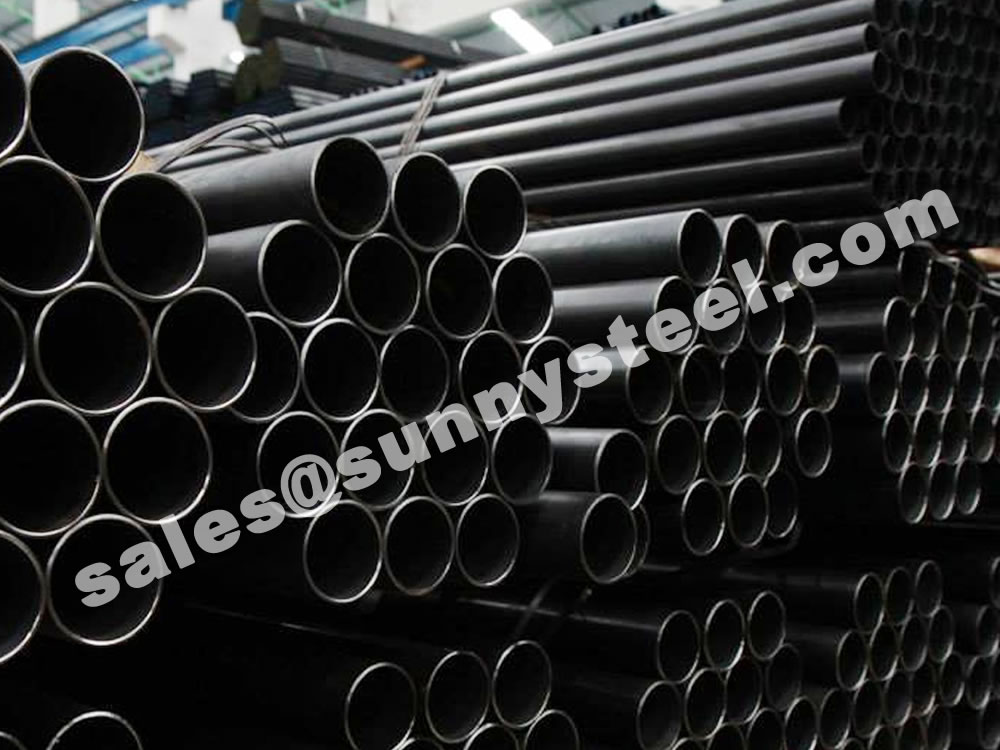
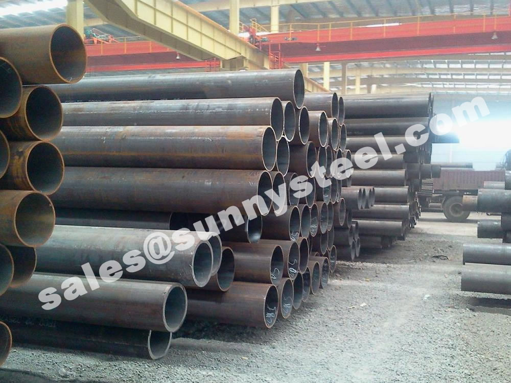
Low cost: the low raw material cost and manufacturing cost make it prices more competitive than longitudinal seam submerged-arc welded pipes and seamless pipes.
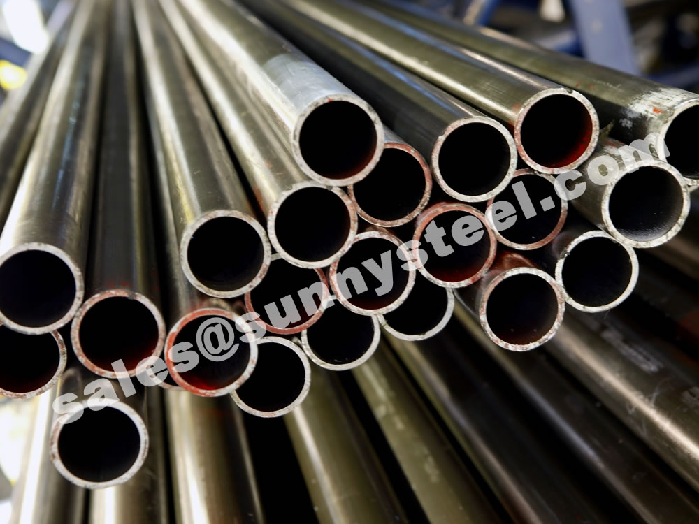
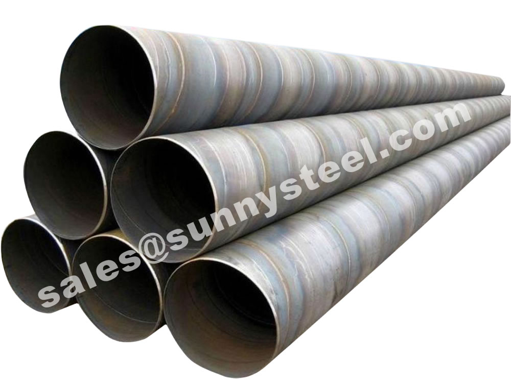
High Weld Seam Security: As a result of special welding method of melting parent metal together, without filler metal, the weld property is better than submerged-arc welded pipes; and the weld seam is much shorter than spiral seam welded pipes, the seam security is greatly improved.
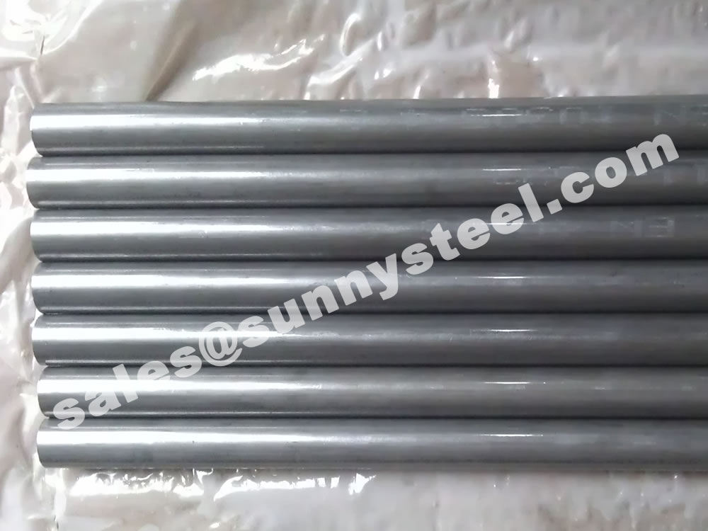
Wide Range: ERW pipes can be applied with a wide range of thickness / diameter ratio, covering hundreds of specifications.
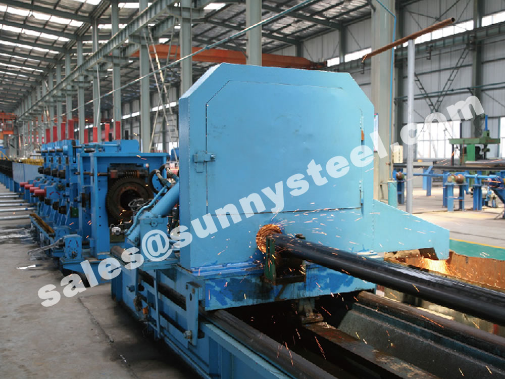
This article provides an overview of electric resistance welding (ERW). It dicusses high-frequency ERW (contact and induction) and rotary wheel contact welding (AC, DC, and square wave). It describes the differences among the processes, as well as the power supplies and weld rolls.
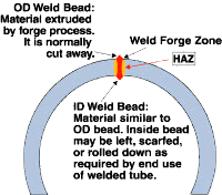
Several electric resistance welding (ERW) processes are available for tube and pipe production. While each process has different characteristics, all ERW processes have one thing in common–all of them produce a forged weld.
A forged weld is created by applying a combination of heat and pressure, or forging force, to the weld zone. A successful forged weld uses the optimum amount of heat, which is normally slightly less than the melting point of the material, and a nearly simultaneous application of circumferential pressure to the section, which forces the heated edges together (see Figure 1).
As the name implies, the heat generated by the weld power is a result of the material’s resistance to the flow of electrical current. The pressure comes from rolls that squeeze the tube into its finished shape.
The two main types of ERW are high-frequency (HF) and rotary contact wheel.
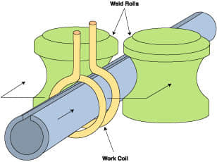
Figure 2 / Object
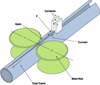
Figure 3 / Object
The two main aspects of HF welding are processes and power supplies. Each of these can be broken down further into subcategories. Processes. The two HF welding processes are HF contact and HF induction. In both processes, the equipment that provides the electrical current is independent from the equipment that supplies the forge pressure. Also, both HF methods can employ impeders, which are soft magnetic components located inside the tube that help to focus the weld current in the strip edges.
HF Induction Welding. In the case of HF induction welding, the weld current is transmitted to the material through a work coil in front of the weld point (see Figure 2). The work coil does not contact the tube–the electrical current is induced into the material through magnetic fields that surround the tube. HF induction welding eliminates contact marks and reduces the setup required when changing tube size. It also requires less maintenance than contact welding.
It is estimated that 90 percent of tube mills in North America use HF induction welding.
HF Contact Welding. HF contact welding transfers weld current to the material through contacts that ride on the strip (see Figure 3). The weld power is applied directly to the tube, which makes this process more electrically efficient than HF induction welding. Because it is more efficient, it is well-suited to heavy-wall and large-diameter tube production.
Power Supplies. HF welding machines also are classified by how they generate power. The two types are vacuum tube and solid-state. The vacuum tube type is the traditional power supply. Since their introduction in the early ’90s, however, solid-state units have quickly gained prominence in the industry. It is estimated that between 500 and 600 of each type are operating in North America.

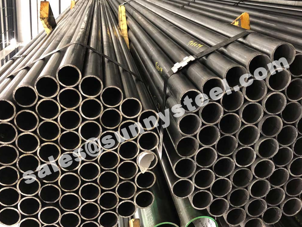
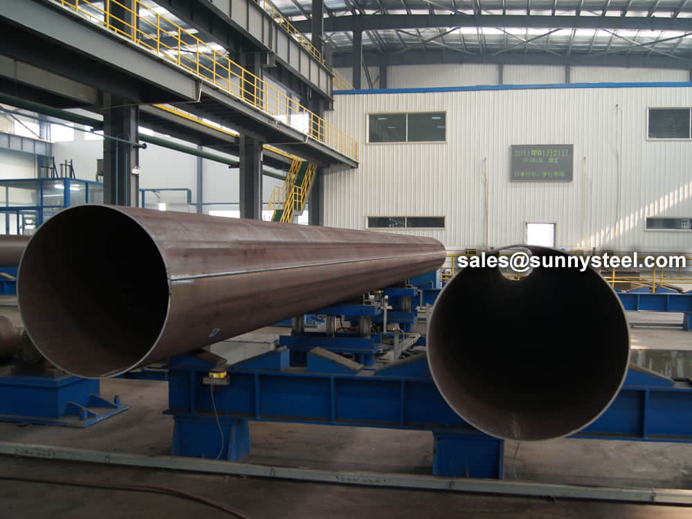
While manufacturing ERW steel pipes, only high-quality, continuous-cast, fully killed, control-rolled, fine-grain, low-carbon steel is used.
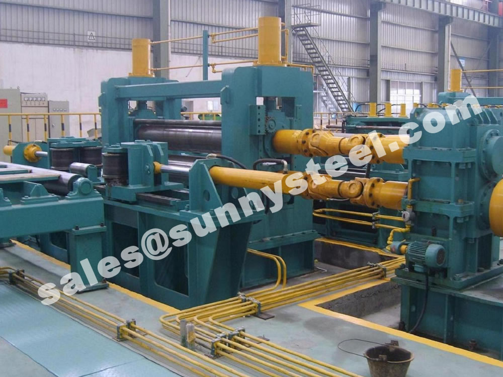
From the analysis data of ERW steel pipe scrapping, it can be seen that the roll adjustment process plays a very important role in the production of welded pipes. That is, in the production process, if the rolls are damaged or worn seriously, some rolls in the unit should be replaced in time, or a certain type of straight seam welded steel pipe should be continuously produced in sufficient quantities, and the entire set of rolls should be replaced.
When replacing the welded pipe, the roll needs to be adjusted accordingly to ensure the quality of the welded pipe. On the contrary, if the roll is not adjusted properly, it is easy to cause defects such as torsion, lap welding, edge undulation, indentation, scratches and even large ovals on the surface of the welded pipe on the protrusion and the pipe body.
The following is an introduction to the operation method of roll adjustment that should be mastered when changing rolls.
First of all, if you want to change the specifications of ERW steel pipes, generally speaking, you should replace the whole set of rolls. The steps to adjust the roll shape are: firstly pull the steel wire at the inlet and outlet of the unit out of the center line, adjust the pass shape of each frame on the center line, and make the forming line meet the technical requirements.
In order to ensure the welding quality of ERW steel pipes, the forming rolls, guide rolls, squeeze rolls, and sizing rolls need to be adjusted once after the rolls are replaced as required, and then focus on adjusting the closed-cell type, guide rolls, and sizing rolls. Squeeze rollers. The role of the guide roller is to control the direction of the weld seam and the height of the bottom line of the welded pipe, reduce the edge extension, control the rebound of the edge of the tube billet, and ensure that the weld seam enters the extrusion roller straight and without deformation.
In short, during the welding process of the welded pipe, when the welder is running at a low speed, the welder must pay close attention to the rotation of the rollers of each part of the welded pipe, and adjust the rollers at any time. Ensure that the welding quality and process size of the welded pipe meet the specification requirements.
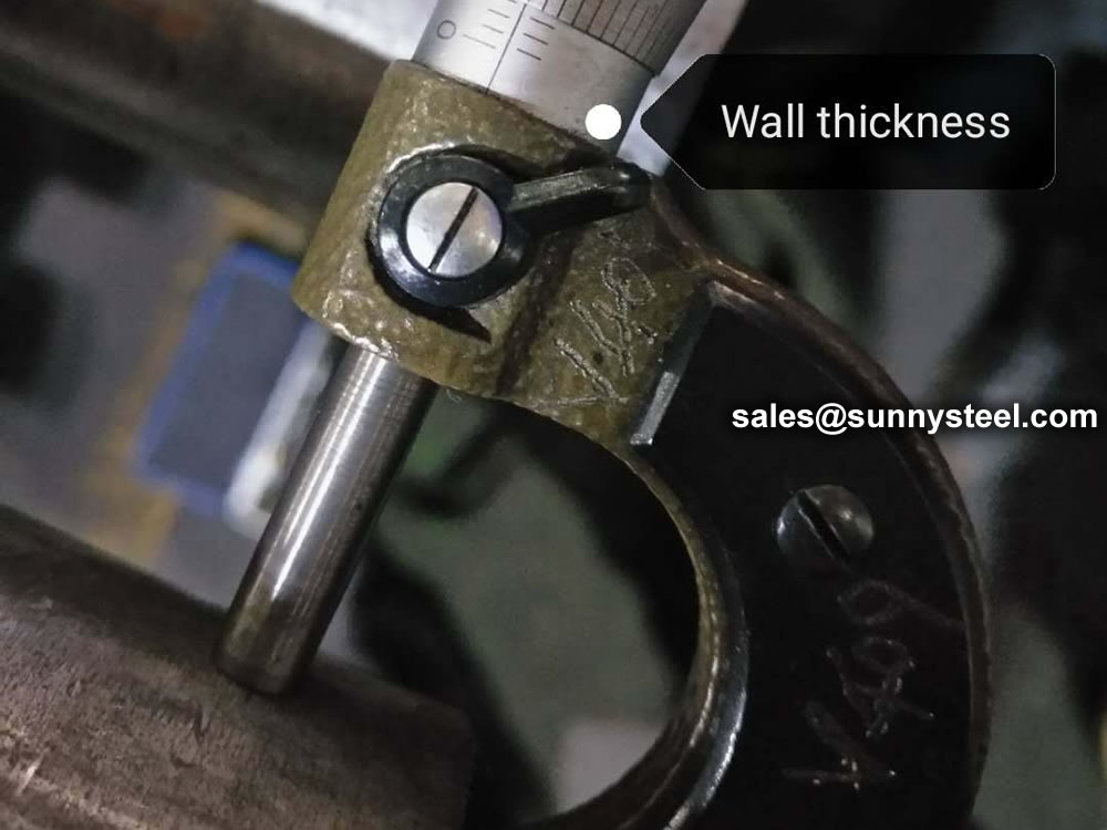
The quality assessment process of ERW pipes includes online non-destructive testing, metallographic inspection, flattening and flaring destructive tests, and hydrostatic testing.
Evaluation process:
The detection arm of the rotary flaw detection station is placed on the longitudinal welded pipe production line, the position of the weld seam is observed through the camera, and the front and rear positions of the probe are adjusted with the operating lever so that the weld seam and the laser overlap, and the parameters are saved. Input steel strip coil number through DATASERVR and DACQ computer. Observe the waveform display on the flaw detection interface. When the waveform exceeds the alarm line, compare the thickness measurement information to judge whether it is a defect wave or an interference wave signal, and visually check whether the pipeline waveform exceeds the alarm line. If the waveform exceeds the alarm line, an alarm will be issued. Stop in time and readjust the welding parameters.
(1) Weld metallographic microstructure. It is generally required to judge whether the coarse structure in the heat-affected zone of the weld is completely eliminated after heat treatment, whether it is basically consistent with the structure of the base metal, and whether there is a fusion line of inclusions in the weld. Generally speaking, the weld has no inclusions, no microcracks, and a clear organizational structure, indicating a weld mesh.
(2) Metal streamlined. In high-frequency welding, the proximity effect and skin effect cause the strip edges to be in a molten and semi-molten state. Under the pressure of the squeeze roller, the weld metal flows in and out, and the base metal on both sides of the weld rises to form a clamp. This angle is called the streamline angle α, and the welding seam is generally determined to be 40°~70° as qualified; if it exceeds this range, the welding process parameters need to be adjusted in time.
(1) Flattening test. Cut about 100mm of welded pipe and place it under the hydraulic press. The position of the weld seam is perpendicular to the pressurizing direction of the hydraulic press. Start the hydraulic pressure and slowly press down on the welded pipe until it is 3/4 of the diameter. Check the welds for cracks. If there are no cracks, weld the grid; if there are cracks, adjust the welding process parameters in time.
(2) Flaring test. Cut a welded pipe of about 100mm and place it on the conical top core; put the conical top core under the oil press, start the oil pressure, and slowly press down the welded pipe. When the flaring reaches 8%, check whether the weld is cracked. If there are no cracks, weld the grid; if there are cracks, adjust the welding process parameters in time.
During the hydrostatic test, first use the flange to clamp the welded flange to seal the two ends of the welded pipe, then inject water into the pipe, and gradually increase the pressure to the pressure required by the relevant standards. After a certain period of time, visually check the welding condition of the pipe body. Are there any leaks at the seams. If there is no leakage, weld the grid; if there is leakage, adjust the welding process parameters in time. During the hydrostatic test, there is no leakage at the weld seam, and the weld seam is welded together. This is also the last process of welded pipe quality inspection.
| Product Name | Executive Standard | Dimension (mm) | Steel Code / Steel Grade |
|---|---|---|---|
| Casting | API 5CT | Ø48.3~273 x WT2.77~11.43 | J55, K55, N80, L80 |
| Tubing | API 5CT | Ø48.3~273 x WT2.77~11.43 | J55, K55, N80, L80, H40 |
| Product Name | Executive Standard | Dimension (mm) | Steel Code / Steel Grade |
|---|---|---|---|
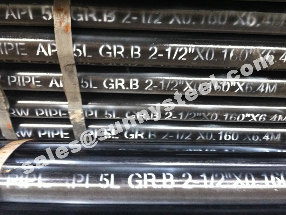
| Line Pipes | API 5L | Ø60.3~273.1 x WT2.77~12.7 | A25, A, B, X42, X46, X52, X56, X60, X65, X70, X80 |
| Product Name | Executive Standard | Dimension (mm) | Steel Code / Steel Grade |
|---|---|---|---|
| Electric-Resistance-Welded Steel Pipes | ASTM A135 | Ø42.2~114.3 x WT2.11~2.63 | A |
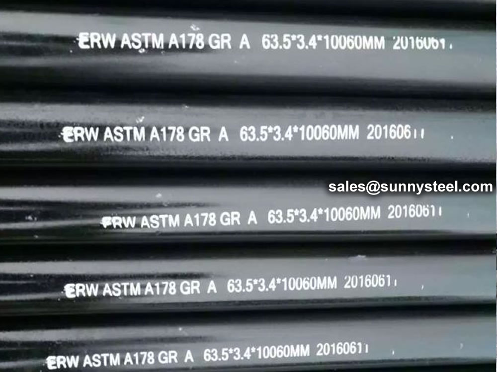
| Electric-Resistance-Welded Carbon Steel and Carbon-Manganese Steel Boiler and Superheater Tubes | ASTM A178 | 42.2-114.3 x 2.11-2.63 | A, C, D |
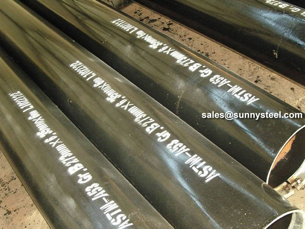
| ERW and Hot-dip Galvanized Steel Pipes | ASTM A53 | Ø21.3~273 x WT2.11~12.7 | A, B |
| Pipes for Piling Usage | ASTM A252 | Ø219.1~508 x WT3.6~12.7 | Gr.2, Gr.3 |
| Tubes for General Structural Purpose | ASTM A500 | Ø21.3~273 x WT2.11~12.7 | Gr.2, Gr.3 |
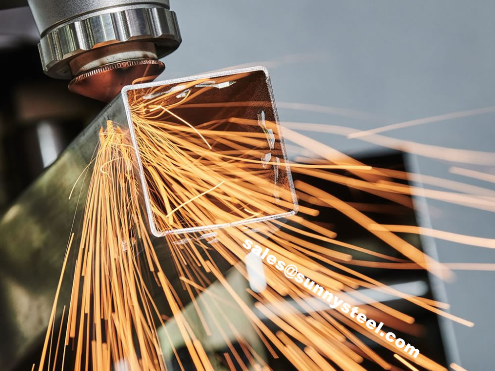
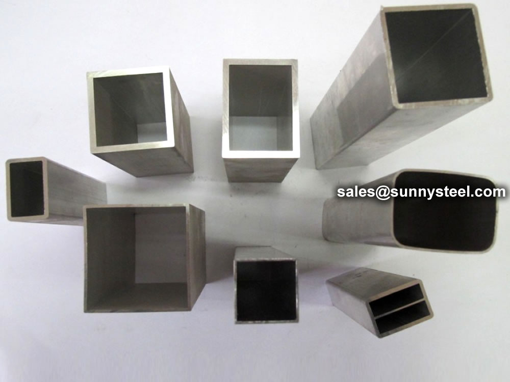
| Square Pipes for General Structural Purpose | ASTM A500 | 25 x 25~160 x 160 x WT1.2~8.0 | Carbon Steel |
| Product Name | Executive Standard | Dimension (mm) | Steel Code / Steel Grade |
|---|---|---|---|
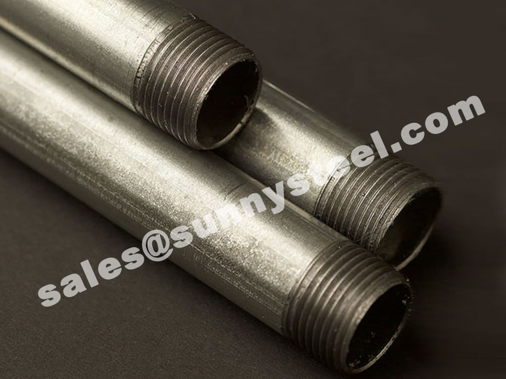
| Threaded Steel Pipes | DIN 2440 | Ø21~164 x WT2.65~4.85 | Carbon Steel |
| Product Name | Executive Standard | Dimension (mm) | Steel Code / Steel Grade |
|---|---|---|---|
| Screwed and Socketed Steel Tubes | BS 1387 | Ø21.4~113.9 x WT2~3.6 | Carbon Steel |
| Scaffolding Pipes | EN 39 | Ø48.3 x WT3.2~4 | Carbon Steel |
| Product Name | Executive Standard | Dimension (mm) | Steel Code / Steel Grade |
|---|---|---|---|
| Carbon Steel Tubes for General Structure Purpose | JIS G3444 | Ø21.7~216.3 x WT2.0~6.0 | Carbon Steel |
| Carbon Steel Tubes for Machine Structure Purpose | JIS G3445 | Ø15~76 x WT0.7~3.0 | STKM11A, STKM13A |
| Carbon Steel Pipes for Ordinary Piping | JIS G3452 | Ø21.9~216.3 x WT2.8~5.8 | Carbon Steel |
| Carbon Steel Pipes for Pressure Service | JIS G3454 | Ø21.7~216.3 x WT2.8~7.1 | Carbon Steel |
| Carbon Steel Rigid Steel Conduits | JIS G8305 | Ø21~113.4 x WT1.2~3.5 | G16~G104, C19~C75, E19~E75 |
| Carbon Steel Rectangular Pipes for General Structure | JIS G3466 | 16 x 16~150 x 150 x WT0.7~6 | Carbon Steel |
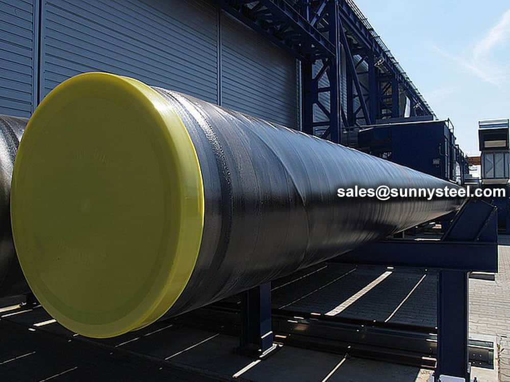
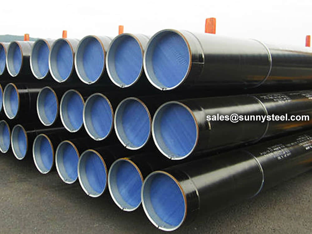
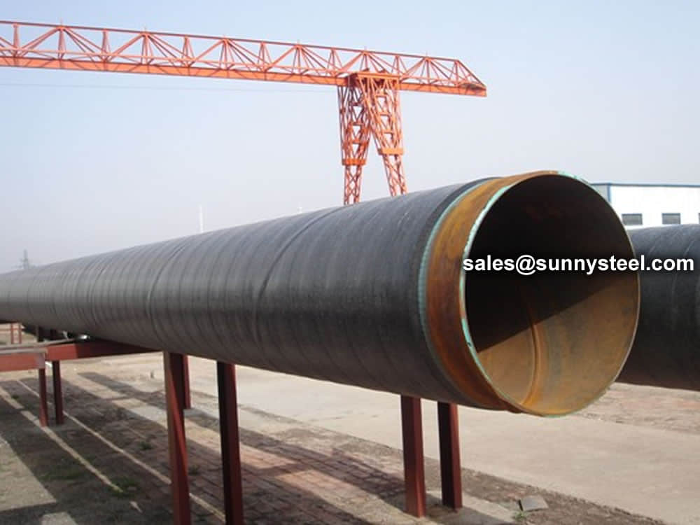
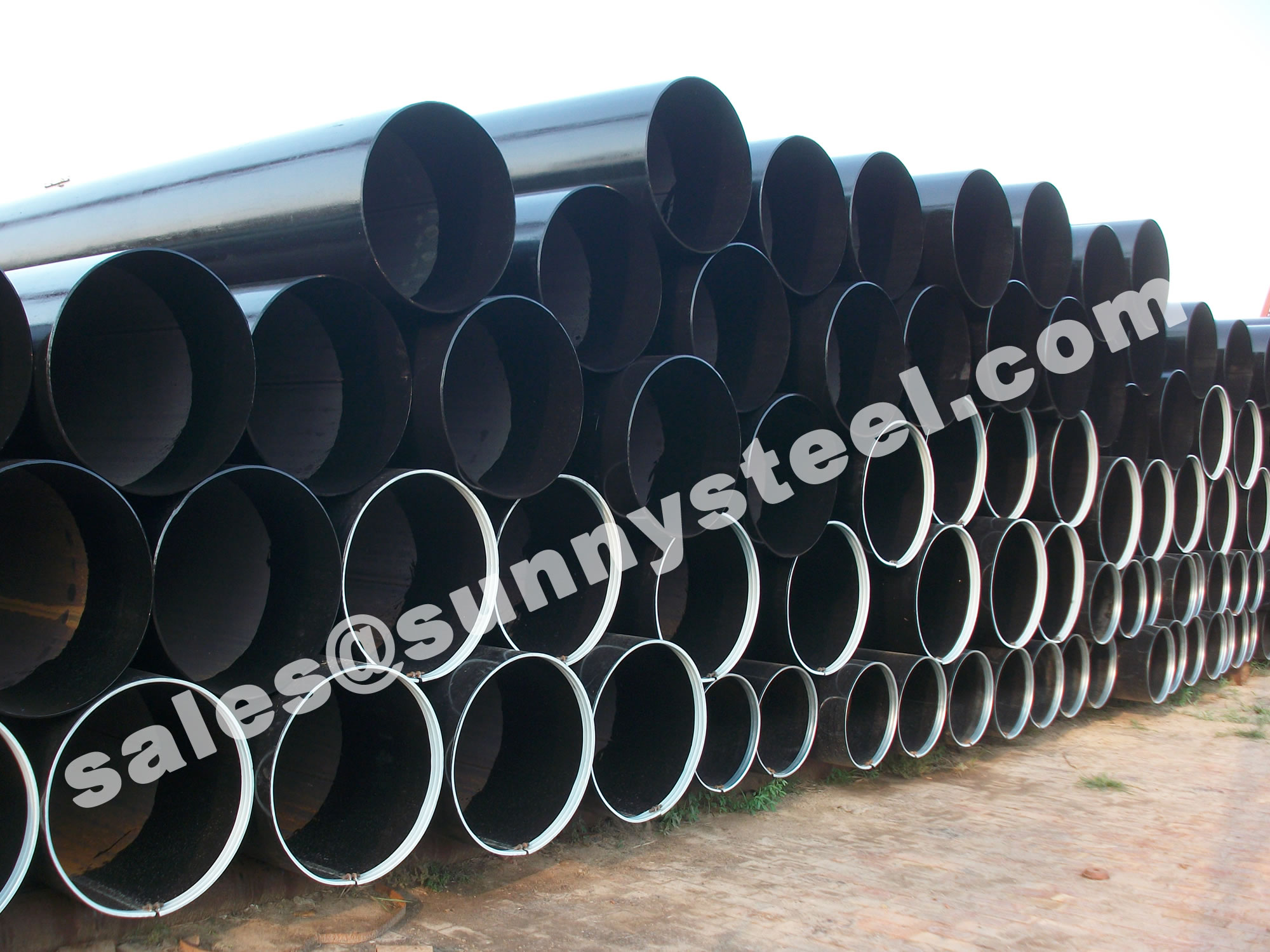
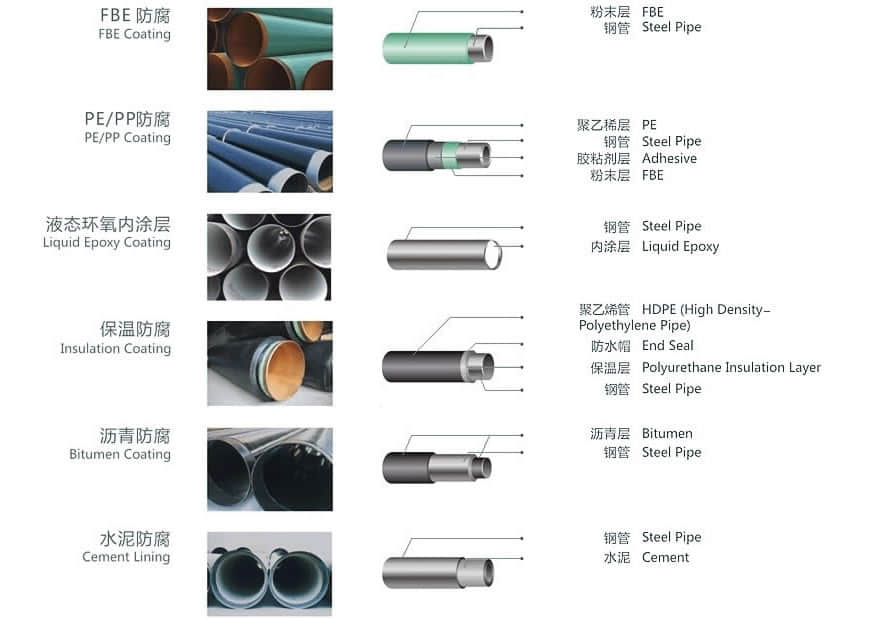
Pipeline coating is the most consistent and successful solution for protecting ERW pipes from corrosion, from moisture, other harmful chemicals.
Anti-corrosion steel pipe is processed through the preservation process, which can effectively prevent or slow down the process in the transport and use of chemical or electrochemical corrosion reaction of steel pipe.
Therefore pipe anti-corrosion layer is an important barrier to prevent soil erosion. A well-known foreign scholar put forward” 3PE france protective layer”, so far, anti-corrosion methods is widely used.
Coated pipes offer high resistance to corrosion on pipes and provide many benefits such as:
The basic principles of urban gas pipeline coating selection:


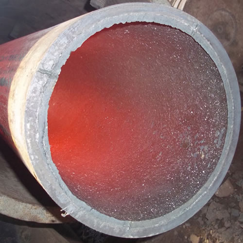
Ceramic lined pipe is made through self-propagating high-temperature synthesis (SHS) technique.
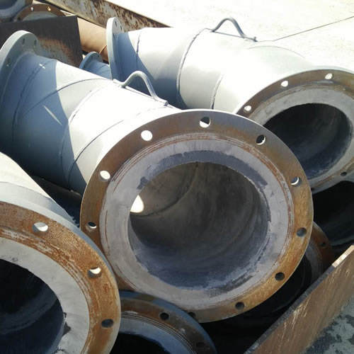
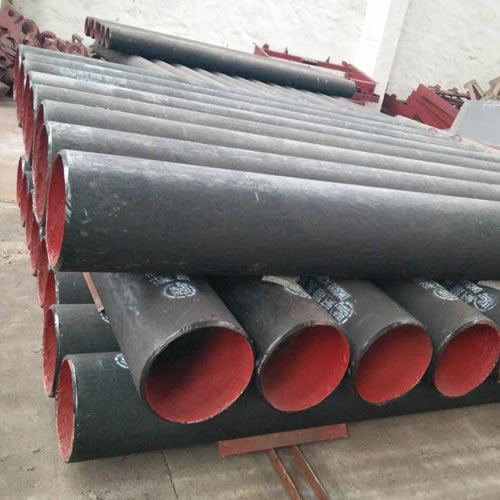
Cast basalt lined steel pipe is composed by lined with cast basalt pipe, outside steel pipe and cement mortar filling between the two layers.
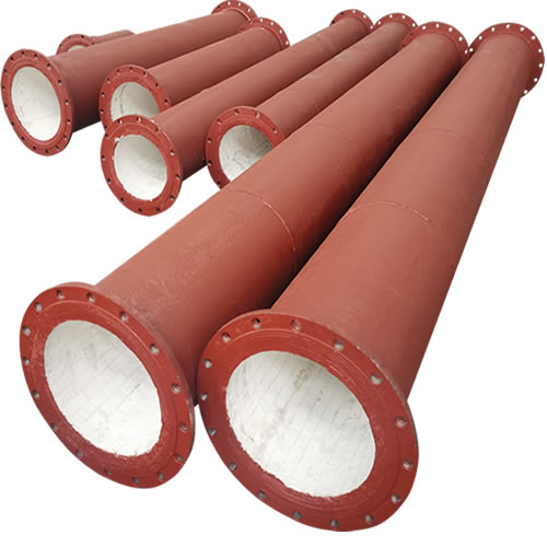
Ceramic tile lined pipes have very uniform coating of specially formulated ceramic material that is affixed to the inner of the pipe.
The material of the rare earth alloy wear-resistant pipe is ZG40CrMnMoNiSiRe, which is also the grade of rare earth alloy steel.
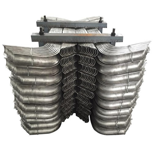
Tubes Erosion Shields are used to protect boiler tubing from the highly erosive effects of high temperatures and pressures thereby greatly extending tube life.
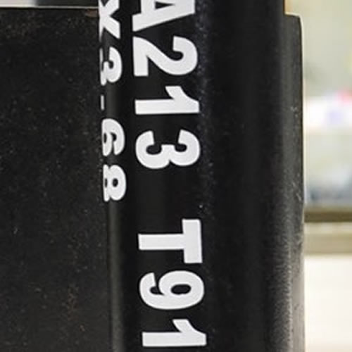
The ASTM A213 T91 seamless tubes are primarily used for boiler, superheater, and heat-exchanger.

When you partner with Sunny Steel, you can stop worrying about meeting deadlines thanks to our responsive and timely service. You'll also say goodbye to unnecessary shopping around. Instead, you'll get white glove service from an expert who understands your needs and can get you the materials you need quickly.