Integral Spiral Finned Tube | The Ultimate Guide for Industrial Heat Exchange Projects - Sunny Steel Industrial Pipe Product

Integral Spiral Finned Tube

The Ultimate Guide for Industrial Heat Exchange Projects

One-piece hot extruded integral spiral finned tube eliminates contact thermal resistance, delivers long service life under high temperature, ash-laden and corrosive flue gas working conditions.

What is Integral Spiral Finned Tube?

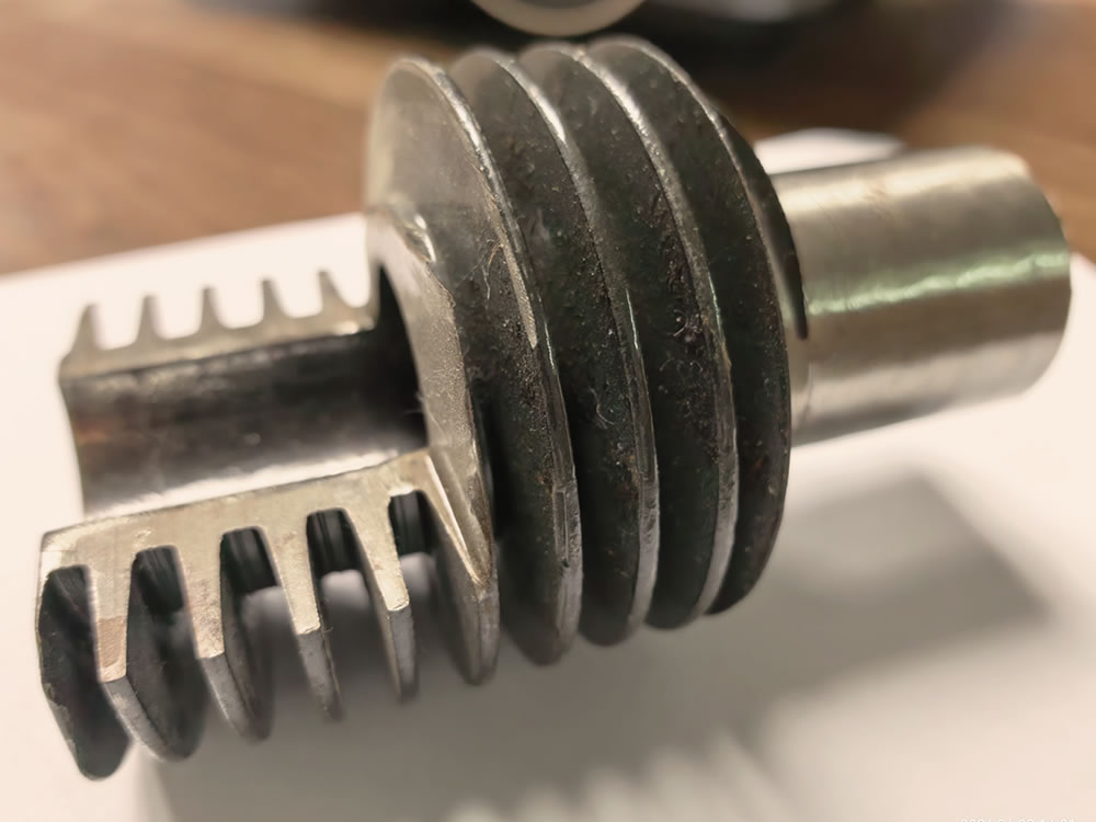
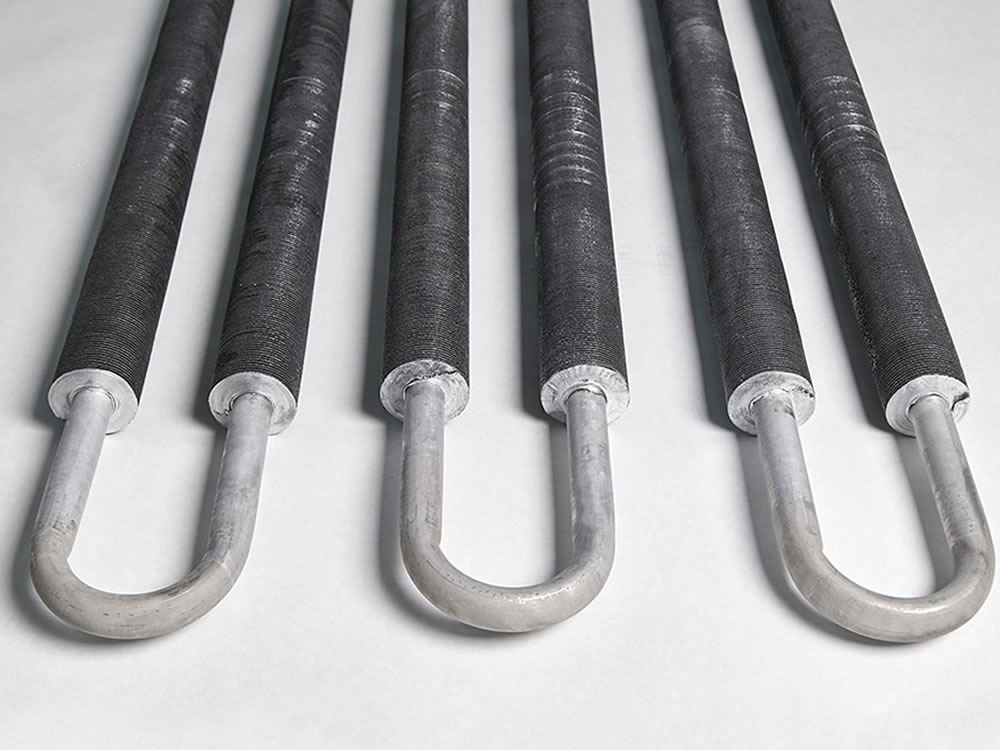
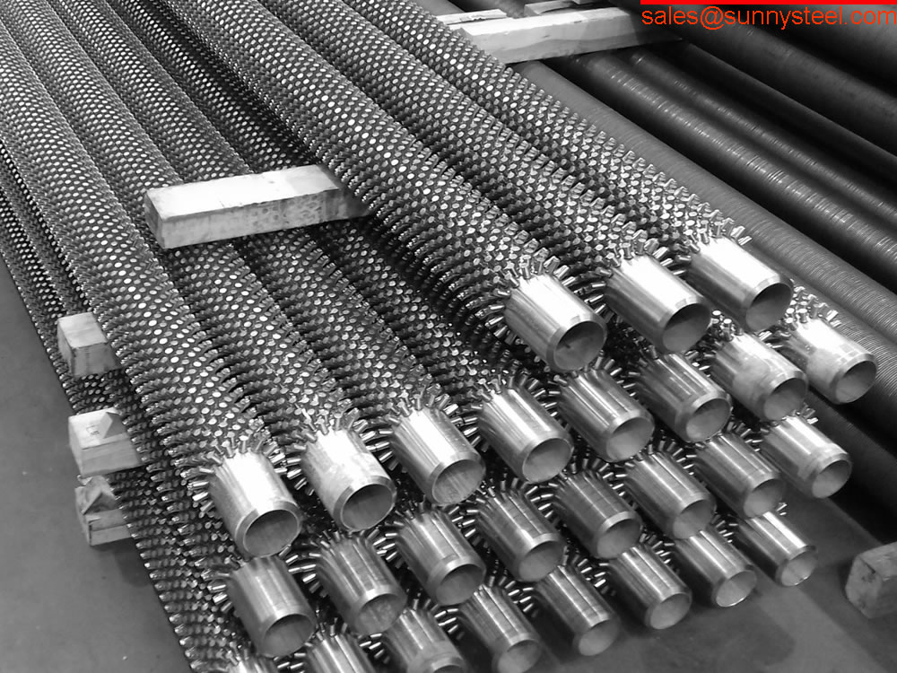
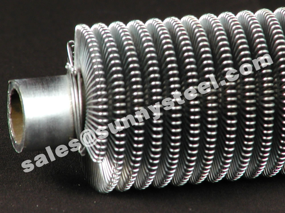
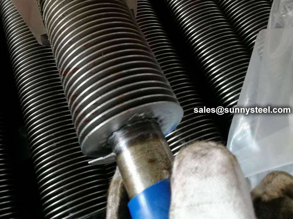
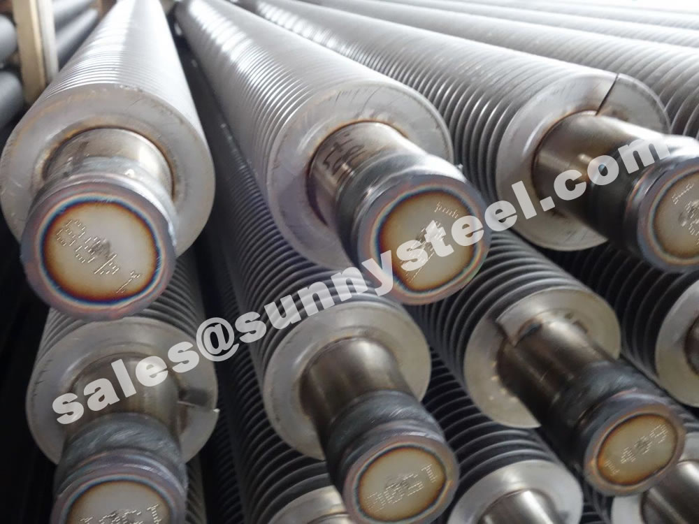
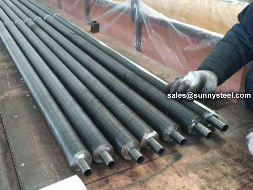
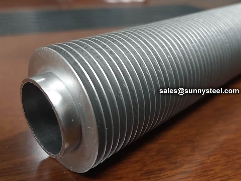
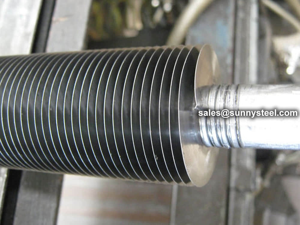
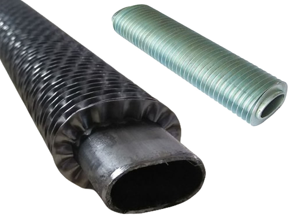
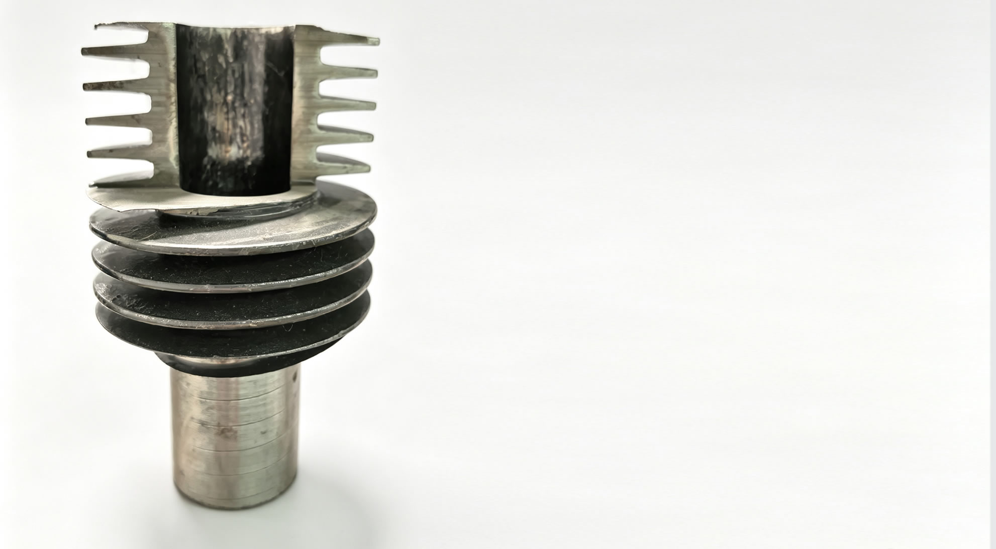
Integral spiral finned tube (also known as integral rolled circular finned tube, integral finned tube) is a high-efficiency heat transfer component optimized for harsh industrial thermal conditions. It is not a regular welded fin tube; instead, it is milled from a single piece of thick-walled seamless steel tube via hot extrusion or hot rolling process, with continuous spiral fins formed as an integral part of the base tube — no welding, no brazing, no mechanical bonding between the fin and base tube. This eliminates the thermal resistance caused by gaps or inconsistent fusion in traditional assembled fin tubes, ensuring uninterrupted heat transfer from the innermost wall of the base tube to the outermost edge of the fins.

As a core heat exchange component, this monolithic finned tube solves typical drawbacks of conventional heat transfer tubes under high-temperature, high-pressure and corrosive flue gas, including low heat transfer efficiency, fin shedding, heavy ash fouling and short service lifespan. It becomes the preferred heat transfer element for thermal power, petrochemical and waste heat recovery large-scale energy projects due to balanced heat transfer efficiency, mechanical strength and stable long-term operation.

Basic Definition & Manufacturing Process

Product Definition

Integral spiral finned tube is a high-strength, high-efficiency heat exchange element manufactured through precision hot-working forming. Its core competitive advantage lies in the integrated monolithic structure: spiral fins and base tube are formed from identical seamless thick-wall steel without any welds or connection seams. This structural feature completely avoids hidden risks existing on welded fin tubes, such as fin detachment, incomplete fusion and gap electrochemical corrosion.
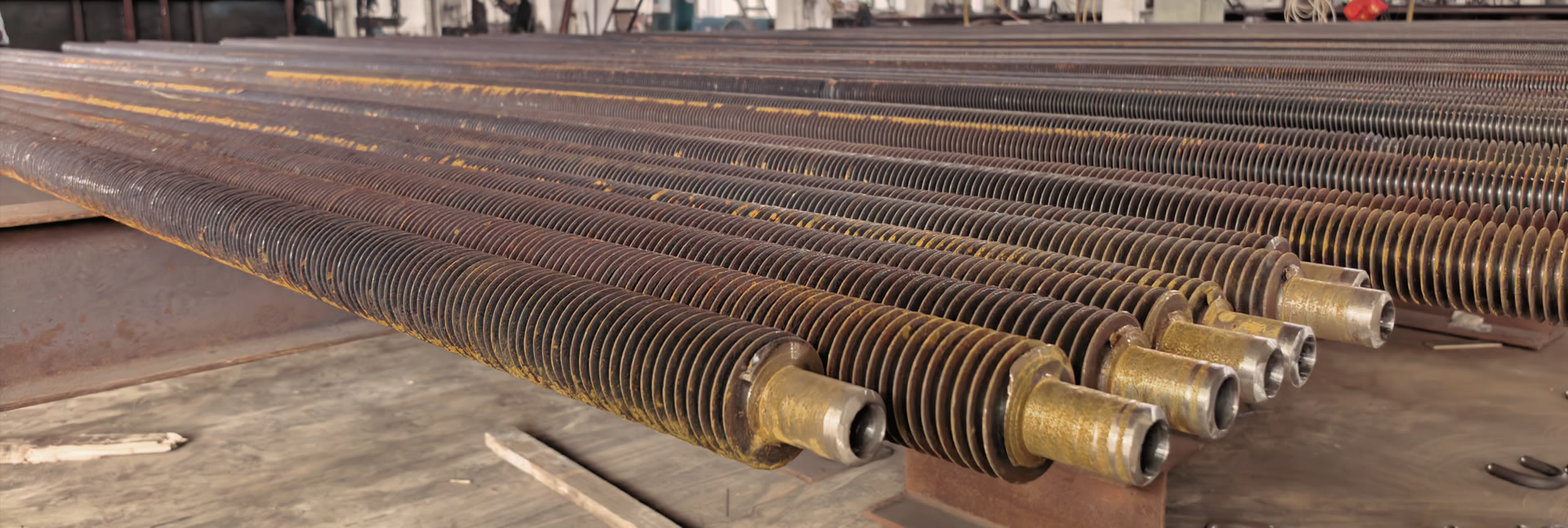
Complete Production Flow

  1. Precision Material Preparation: Adopt qualified thick-wall seamless steel tube raw material, with full pre-inspection including chemical composition analysis, mechanical test and dimensional tolerance measurement to satisfy high-temperature hot rolling requirements.
  2. Medium-Frequency Induction Heating: Evenly heat base tube to 900°C-950°C by 2000HZ~2500HZ medium-frequency heating system, guarantee uniform metal softening and prevent uneven wall thinning during rolling.
  3. One-Time Spiral Fin Forming: Heated tube passes through 120° equally distributed three sets rolling cutters, radial metal extrusion forms continuous spiral fins in single pass. Fin height, pitch and thickness are precisely controlled, sharing consistent metallurgical grain with parent tube.
  4. Post-Forming Precision Treatment: Slow cooling for residual stress removal, shot blasting for oxide scale elimination, straightening for radial runout correction. Custom passivation or anti-corrosion coating available for corrosive flue gas working scenarios.
  5. Full-Range Multi-Stage Quality Inspection: 100% surface visual inspection, eddy current nondestructive test, key dimension measurement. Batch sampling for hydrostatic pressure test and heat transfer coefficient verification, all test records fully traceable.
Integral Spiral Finned Tube for Heat Exchanger

Core Performance Advantages

Exceptional Heat Transfer Performance

Integral forming expands effective heat exchange area significantly, without contact thermal resistance between fin and tube. φ32×3mm tube with 10mm fin height & 8.5mm pitch owns 4x heat transfer area vs smooth tube, 1.5x vs wrapped welded fin tube. Spiral fins disrupt flue gas laminar boundary layer, overall heat transfer coefficient over 100% higher than plain tubes, effectively cutting system fuel consumption.

Superior Anti-Wear Performance

Consistent metallurgical structure eliminates weak connection points; dune-shaped fin root optimizes flue gas flow field and lowers local ash scouring intensity. Spiral flow suppresses Karman vortex street which causes concentrated abrasion, uniform tube wall thickness maintained under long-term ash-laden flue gas operation, avoiding tube perforation failure.

Enhanced Structural Rigidity & Vibration Resistance

High section inertia allows maximum support span up to 5.28m, nearly double smooth tube’s 2.71m limit. Rigidity attenuation is minimal even at working temperature up to 460°C, effectively preventing span bending and vibration fatigue fracture under high-temperature flue gas impact.

Excellent Anti-Fouling Property

Rotational flue gas flow guided by spiral fins eliminates low-speed recirculation dead zone where ash accumulates. Burr-free smooth fin surface reduces ash adhesion, minor ash sediment can be cleaned by regular steam soot blowers, stable heat transfer efficiency without frequent shutdown cleaning.

Extend Service Life

No fin-tube gap corrosion or shedding risk, strong thermal & mechanical shock resistance. Service life reaches 7~8 years, 2-3 times longer than smooth tube or welded fin tube under identical harsh flue gas conditions, drastically cutting tube bundle replacement frequency and unplanned downtime loss.

Full-Spectrum Comprehensive Economic Benefits

Stable heat transfer without long-term efficiency attenuation, lower daily maintenance workload, wide load adaptation range. Though initial procurement cost is slightly higher, energy saving, maintenance reduction and long service cycle bring obvious overall lifecycle cost reduction for large industrial projects.

Material Selection & Technical Specifications

Available Material Grades & Applicable Working Conditions

Material Category Standard Grades Max Continuous Temp Applicable Scenarios
Carbon Steel ASTM A179, ASTM A210 Gr.C ≤450°C Medium-low temp boiler economizer, heating furnace waste heat recovery
Alloy Steel SA213 T5, T9, T11 ≤550°C High-temperature boiler superheater, weak corrosive flue gas
Stainless Steel TP304, TP316L ≤550°C Acidic sulfur-containing flue gas, chemical waste heat recovery

Customizable Structural Parameter Range

Parameter Item Custom Range
Base Tube Outer Diameter 15.88mm ~ 50.80mm (5/8" ~ 2")
Base Tube Wall Thickness 2mm ~ 6mm, customized per pressure demand
Fin Height 8mm ~ 16mm, adjusted for anti-wear & heat transfer
Fin Pitch 5mm ~ 12mm, optimized for ash fouling resistance
Fin Thickness 0.8mm ~ 2.0mm
Single Tube Length Max 18 meters, custom length available

All structural dimensions can be precisely adjusted according to flue gas ash content, operating temperature and customer heat exchanger drawing requirements.

Manufacturing & Inspection Compliance Standards

  • ASTM A498/A498M: Standard specification for integral seamless carbon steel finned tubes
  • ASTM A1012/A1012M: Standard for alloy & stainless steel integral fin tubes for high-temperature service
  • NB/T 47030-2013: Chinese industrial standard for boiler spiral finned tubes
  • GB/T 15386-2017: National standard for industrial heat exchange fin tube performance test

All finished tubes supply EN 10204 3.1 factory test certificate; SGS/BV third-party inspection documents are available for EPC overseas projects.

Main Industrial Application Fields

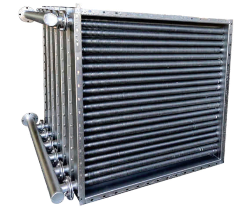
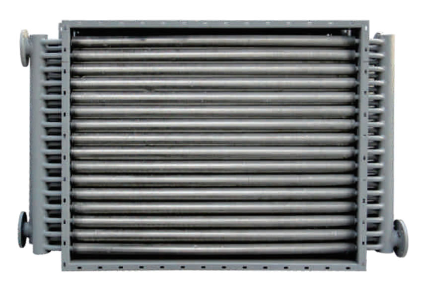
  • Thermal Power & Industrial Boiler: Economizer, air preheater and flue gas waste heat recovery sections of circulating fluidized bed boilers, utility power station boilers and industrial waste heat boilers.
  • Petrochemical Industry: Crude oil preheaters, process gas coolers, residual oil waste heat recovery equipment, resistant to high temperature, pressure and sulfur medium corrosion.
  • Waste Heat Recovery Equipment: Flue gas heat recovery for waste incineration plant, steel blast furnace and coke oven, recycle low-temperature high-dust waste heat for power generation and factory heating.
  • Other Industries: Large industrial HVAC condenser, pharmaceutical process medium heat exchange, food factory clean steam generation and waste heat recycling.

Why Select Integral Spiral Finned Tube For Your Heat Exchange Project

  1. Higher Energy Saving Efficiency: Heat exchange capacity reaches 1.5~2 times smooth tube bundles, reduce boiler exhaust temperature by 15~25°C, lift overall boiler efficiency by 3%~8% for continuous fuel cost saving.
  2. Compact Equipment Layout: Same heat transfer load requires 40%~50% shorter tube bundle length, lower civil engineering, steel support and installation investment for space-limited project sites.
  3. Reduced Maintenance & Replacement Cost: 2-3x longer service life, less ash cleaning frequency, eliminate regular fin connection inspection, cut daily maintenance labor cost over 50% compared with welded fin tubes.
  4. Stable Long-Term Operation: Avoid fin shedding, joint cracking and efficiency attenuation failures; field data shows product failure rate lower than 10% of traditional tubes, minimize costly unplanned production shutdowns.
  5. Wide Harsh Condition Adaptability: Multiple material grades support working environment up to 550°C, resist acid dew point corrosion and high ash particle abrasion, cover all mainstream industrial waste heat recovery working conditions.

Professional Product Selection Guide

Parameter matching must combine full project working condition data to achieve optimal cost-performance ratio, key judging factors as below:

  • Flue gas medium features: ash content, sulfur/acid corrosion characteristics, determine tube material, fin height and fin pitch.
  • Temperature & pressure index: continuous operating temperature, system design pressure decide base tube wall thickness and alloy material grade.
  • Heat transfer load target: required heat recovery capacity and allowable flue gas pressure drop to configure fin structure combination and tube row layout.
  • On-site installation restriction: equipment space dimension limits maximum single tube length and tube bundle layout size.
  • Project certification standard: ASTM, ASME, NB/T or GB contract specification to confirm factory inspection and third-party certification requirement.

It is recommended to provide full flue gas parameter, heat recovery demand and equipment drawing to manufacturer technical team for professional engineering calculation and customized solution.

Standard Installation & Maintenance Guidelines

Installation Operation Requirements

  • Avoid violent impact and extrusion during transport and installation to prevent spiral fin deformation; store tubes in dry covered storage area to stop surface ash and corrosion.
  • Strictly control tube bundle spacing and flue gas flow direction per drawing, ensure even flue gas distribution and avoid local over-scouring dead zone.
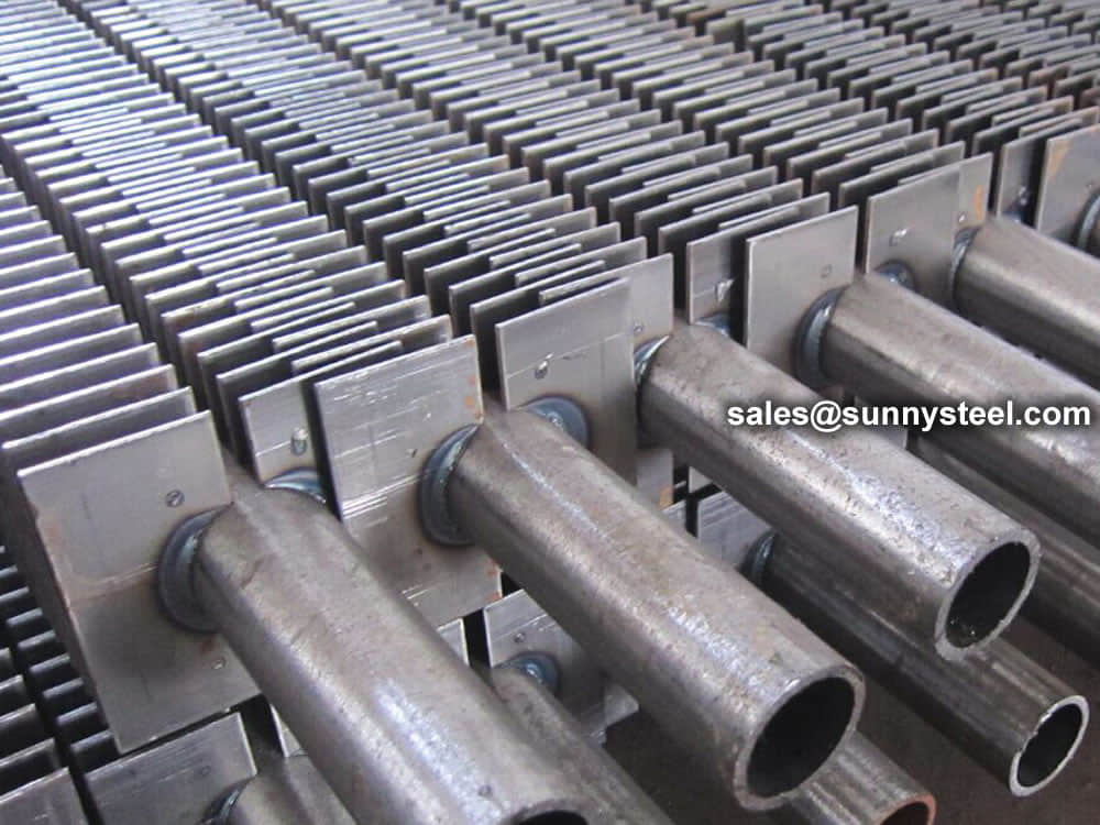
  • Welding between fin tube and header must be operated by certified welders, conduct penetration & radiographic inspection after welding to eliminate leakage defects.
  • Control tube bundle horizontal/vertical tolerance within 1/1000 total length, adjacent tube spacing deviation ±2mm to guarantee uniform airflow.
  • Complete full system hydrostatic test at 1.5x design working pressure, hold pressure over 30 minutes without pressure drop or leakage before formal operation.

Daily Maintenance Suggestions

  • Annual shutdown inspection: check fin surface ash accumulation, windward side abrasion depth; replace tubes if abrasion loss exceeds 10% original fin thickness.
  • Clean tube bundle every 1~3 years based on flue gas ash concentration; adopt high-pressure water washing, avoid strong acid/alkaline detergent eroding fin surface.
  • Regularly calibrate boiler soot blower nozzle position and steam pressure to guarantee ash cleaning effect without extra fin abrasion.
  • Real-time record flue gas inlet/outlet temperature and system pressure; abnormal parameter fluctuation indicates fouling or abrasion problems requiring timely troubleshooting.
  • Control flue gas flow velocity within 8~12m/s to balance heat transfer efficiency and fin anti-wear service life.

Quality Control System & Global Compliance Certifications

Full Process Quality Control

  • Raw material incoming full inspection: chemical composition, mechanical property and dimension test for all seamless tube blank before production line input.
  • First article inspection for each shift after rolling parameter adjustment, only pass all dimension & NDT test can formal batch production start.
  • 100% online inspection during forming process for surface defects and dimensional tolerance.
  • Final factory comprehensive test: hydrostatic pressure test, eddy current & ultrasonic NDT, heat transfer performance sampling test, full surface visual inspection, complete batch traceability production record.

Authorized Global Certifications

Manufacturing system certified by ISO 9001 quality management system, product complies with ASTM, ASME BPVC, NB/T and GB national industrial standards. Additional CE (EU market) and EAC (Eurasian Union) certification documents available upon overseas customer demand; all inspection reports issued in official English version for international EPC project acceptance.

Conclusion

Integral spiral finned tube represents advanced mature heat exchange tube technology for harsh industrial thermal recovery systems. The integrated hot rolling one-piece structure fundamentally overcomes inherent defects of traditional welded fin tubes including fin shedding, performance attenuation and short service life. This product perfectly matches high-efficiency long-cycle operation demand of utility boilers, petrochemical process furnaces and multi-type waste heat recovery equipment.

If you need reliable high-performance heat exchange components to reduce long-term operating cost and improve energy utilization efficiency of your industrial heat exchange project, integral spiral finned tube is your optimal selection. Contact our professional technical sales team for customized technical solution based on your actual flue gas working conditions and heat recovery parameters.
Integral Spiral Finned Tube Integral Spiral Finned construction

Structural Characteristics

Smooth Spiral Transition

Fin root integrates seamlessly with the base tube outer wall, eliminating welding scars and stress concentrations. This improves flue gas fluidity and prevents local corrosion cracking at connection points.

Continuous Metallurgical Grain

Hot rolling induces uniform recrystallization from tube wall to fin edge. No performance discontinuity exists between fin and substrate, ensuring stable mechanical properties under alternating high-temperature flue gas loads.

Ultra-High Structural Rigidity

For a φ32×3 mm tube, the section moment of inertia reaches 167,613 mm⁴4.76× higher than a smooth tube of identical size. Larger allowable support spans reduce hanger quantity and structural vibration risk.

Packaging & Overseas Transportation Standard

Complete Packaging Protection Scheme

  1. Tube End Protection: Custom plastic protective caps seal both tube ends to prevent tube end deformation and internal moisture corrosion.
  2. Surface Anti-Corrosion Wrapping: Entire finned tube wrapped with export-grade crepe paper and shock-absorbing bubble film, isolate salt fog and collision scratch during sea transport.
  3. External Plywood Pallet/Wooden Case: Fixed internal support structure eliminates tube bundle movement; internal waterproof membrane and gap filling buffer material for shock resistance.
  4. Export Reinforced Package: Long-distance sea shipment products fixed on steel support frame, fully covered heat shrink waterproof film for airtight salt fog isolation; wooden packing undergoes heat treatment for phytosanitary compliance.
  5. Standard Shipping Mark: Each case marked with product spec, quantity, weight, "Fragile, Keep Dry, Handle With Care" international handling logo for global logistics identification.

Transportation Loading & Unloading Rules

Steel Radiator
Aluminium Radiator

Heat Transfer Principle of Steel Finned Tubes

Understanding how extended surfaces enhance heat exchanger performance by reducing thermal resistance on the gas side.

Basic Principle

A finned tube heat exchanger is built upon a plain round tube (base tube). The fundamental question is: how can we increase the heat transfer rate of a plain tube? One of the most effective methods is to add extended surfaces—fins—to the outer surface of the tube, typically on the flue gas side.

The overall heat transfer equation is:

Q = U × A × ΔTm

Where:

Q = Total heat transfer rate (W)

U = Overall heat transfer coefficient (W/m²·K), referenced to the base tube outer surface

A = Heat transfer area of the base tube outer surface (m²)

ΔTm = Logarithmic mean temperature difference (K)

When fins are attached to the outer surface, the effective heat transfer area (Aeff) increases to several times—or even dozens of times—the original plain tube area. Although the gas-side heat transfer coefficient (hout) itself remains unchanged, the apparent thermal resistance referred to the base tube area is significantly reduced, thereby enhancing the overall heat transfer process.

Thermal Resistance Analysis

The total thermal resistance of a finned tube can be expressed as:

1/U = 1/hin + δ/λ + 1/(η × hout)

Where:

hin = Inside (tube-side) heat transfer coefficient (W/m²·K)

δ/λ = Wall conduction thermal resistance (m²·K/W)

η = Fin efficiency (0 < η ≤ 1)

hout = Outside (gas-side) heat transfer coefficient (W/m²·K)

In most industrial applications, the gas side (e.g., flue gas) has a much lower heat transfer coefficient than the liquid or steam side. This makes the gas side the controlling thermal resistance. By adding fins, we increase the effective area and reduce this controlling resistance without changing the fluid properties themselves.

Engineering Benefits

  • Reduced Metal Consumption: For a given heat duty Q, the required base tube area is smaller, reducing total metal weight.
  • Compact Design: Smaller heat exchanger footprint for the same duty, saving installation space.
  • Improved Economics: Lower material cost and reduced equipment size lead to better project economics.
  • Enhanced Gas-Side Performance: Even with a low hout, the extended surface compensates effectively.
  • Design Flexibility: Fin height, pitch and thickness can be optimized for specific operating conditions.
  • Better Temperature Matching: More uniform temperature distribution across the heat transfer surface.

Practical Design Considerations

While finned tubes offer significant advantages, several factors must be considered in actual engineering design:

Design Factor Impact on Performance
Fin Efficiency (η) Higher fins increase area but reduce η due to temperature drop along fin height. Optimal fin height must be determined.
Fin Pitch Closer pitch increases area but raises flow resistance and fouling risk. Wider pitch is preferred for dusty or fouling-prone environments.
Gas-Side Velocity Higher velocity improves hout but increases pressure drop and fan power consumption.
Fouling & Ash Deposition In boiler or flue gas applications, fin spacing must accommodate soot-blowing and periodic cleaning.
Material Selection Fin and base tube materials must be compatible with gas chemistry, temperature and corrosion conditions.

Summary

The core principle of finned tube heat transfer is: instead of increasing the heat transfer coefficient, we use extended surface area to overcome the thermal resistance on the low-coefficient side (typically the gas side).

This approach achieves three key objectives simultaneously:

  1. Maintain required heat duty (Q) without increasing fluid velocity or temperature difference.
  2. Reduce base tube material consumption, leading to lighter and more economical equipment.
  3. Minimize equipment footprint, saving space and installation cost.

In practice, successful finned tube design requires balancing fin efficiency, fin geometry, gas-side pressure drop, fouling behavior and material compatibility to ensure long-term, reliable performance.


Engineering Note:
Finned tubes are most effective when the gas-side heat transfer coefficient is significantly lower than the tube-side coefficient (typically hout < 100 W/m²·K vs. hin > 1000 W/m²·K). In such cases, increasing the gas-side area by 5–20× can improve overall U by 2–5×, dramatically reducing equipment size and cost.
Frequently Asked Questions
Integral spiral finned tube is hot rolled from single seamless tube without any welding seam, fin and base tube share identical metallurgical structure with zero contact thermal resistance. Welded fin tube has separate fin strip welded on tube outer wall, existing welding gap thermal resistance, easy fin shedding and local corrosion after long-term high-temperature operation.
Carbon steel type works steadily below 450°C, alloy steel grades T5/T9/T11 support continuous working temperature up to 550°C, TP304/TP316L stainless steel version also suits 550°C high-temperature corrosive flue gas environment.
Under identical high ash flue gas working conditions, smooth tube only lasts 3~4 years, while integral spiral finned tube can operate stably for 7~8 years, extending service life by 2 to 3 times.
Fully customizable. We adjust outer diameter, wall thickness, fin height, fin pitch and single tube length. Technical engineers optimize structural parameters targeted at flue gas ash content, corrosion medium and heat transfer load requirements of each project.
Continuous spiral fin generates rotational flue gas flow and suppresses Karman vortex street low-speed ash accumulation zone. Smooth burr-free fin surface reduces ash adhesion, regular soot blower can clean surface ash efficiently without dead fouling corners.
Standard EN 10204 3.1 factory test certificate including raw material report, dimension inspection record, hydrostatic test and NDT report. SGS, BV third-party inspection, CE and EAC certification documents are available upon customer request.
Yes, mounting mode matches conventional heat exchange tubes, can directly replace smooth tube or welded fin tube without large modification of boiler support hanger and header structure.
Regular annual shutdown inspection of fin abrasion and ash fouling; clean tube bundle every 1~3 years by high-pressure water washing; calibrate soot blower system regularly and control flue gas velocity within 8-12m/s to balance heat efficiency and anti-wear lifespan.
Mainly used for thermal power station boilers, petrochemical waste heat recovery, waste incineration flue gas heat exchange, metallurgical blast furnace waste heat equipment, large industrial HVAC and pharmaceutical/food process heat exchangers.
We adopt multi-layer anti-collision wrapping, fixed plywood pallet/heat-treated wooden case with internal buffer support. All export packages meet international sea transport shockproof and salt fog protection standards to avoid fin extrusion deformation.
Hot Products

【H】 Ceramic lined pipe

Ceramic lined pipe is made through self-propagating high-temperature synthesis (SHS) technique.
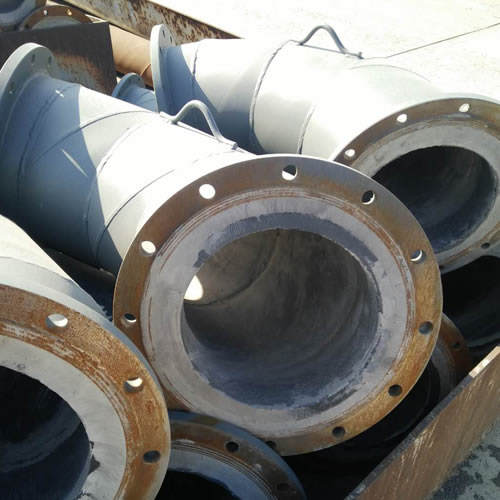
【H】 Cast basalt lined steel pipe

Cast basalt lined steel pipe is composed by lined with cast basalt pipe, outside steel pipe and cement mortar filling between the two layers.
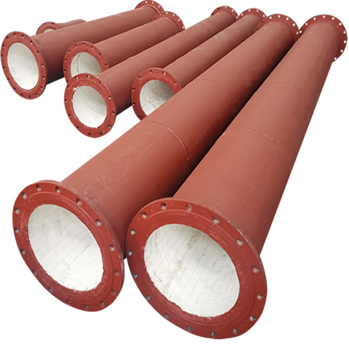
【H】 Ceramic Tile Lined Pipes

Ceramic tile lined pipes have very uniform coating of specially formulated ceramic material that is affixed to the inner of the pipe.
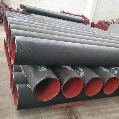
【H】 Rare earth alloy wear-resistant pipe

The material of the rare earth alloy wear-resistant pipe is ZG40CrMnMoNiSiRe, which is also the grade of rare earth alloy steel.
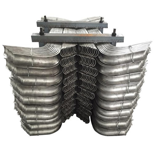
【H】 Tubes Erosion Shields

Tubes Erosion Shields are used to protect boiler tubing from the highly erosive effects of high temperatures and pressures thereby greatly extending tube life.
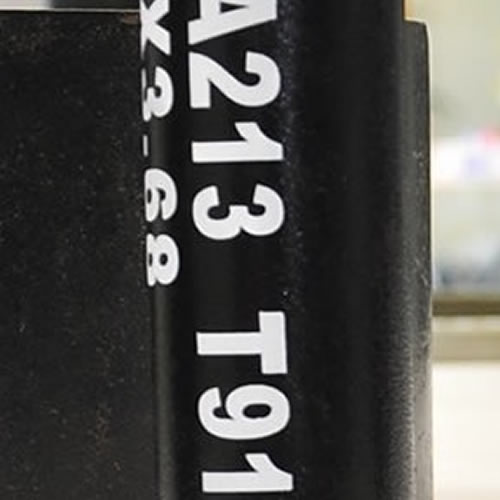
【H】 ASTM A213 T91 Alloy Tube

The ASTM A213 T91 seamless tubes are primarily used for boiler, superheater, and heat-exchanger.

The White Glove Service You Deserve

When you partner with Sunny Steel, you can stop worrying about meeting deadlines thanks to our responsive and timely service. You'll also say goodbye to unnecessary shopping around. Instead, you'll get white glove service from an expert who understands your needs and can get you the materials you need quickly.

application

Materials delivered on-time and at a fair price

application

No delays in production or manufacturing process

application

Meet engineering specifications to ensure top quality

application

World-class customer service ready to help