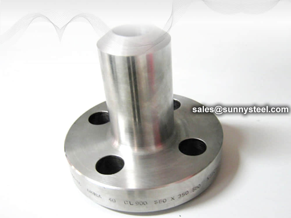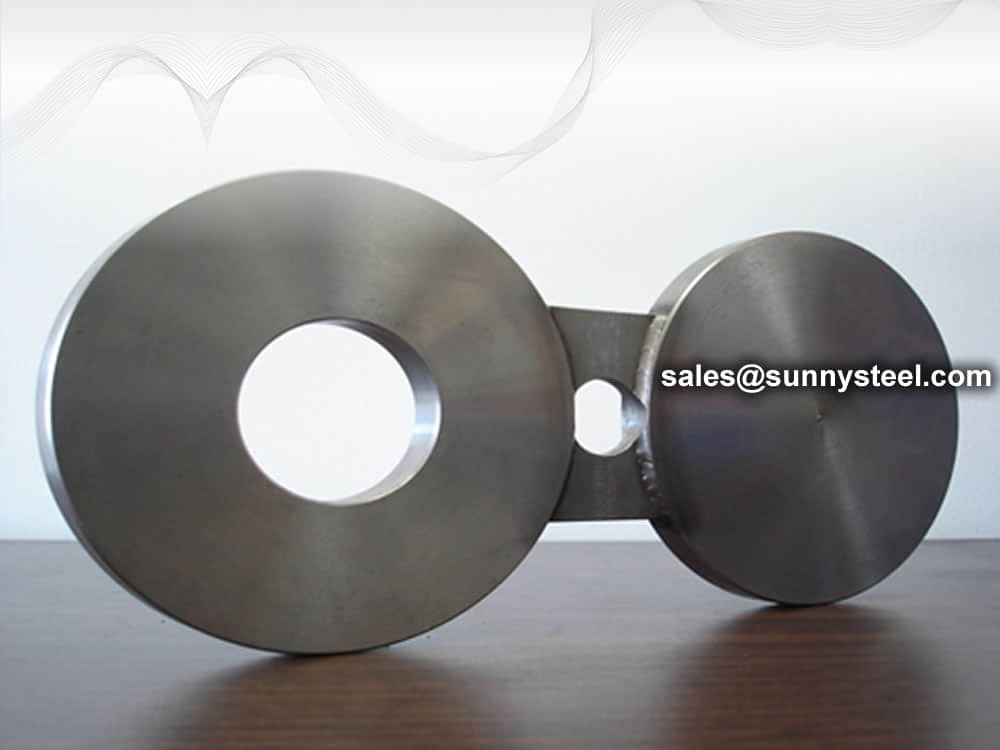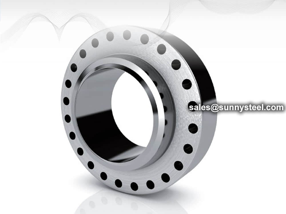
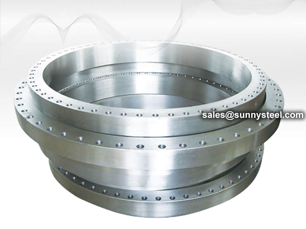
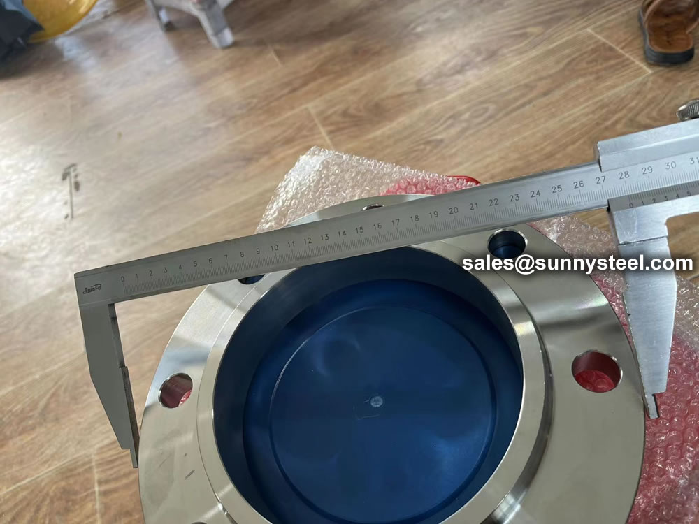
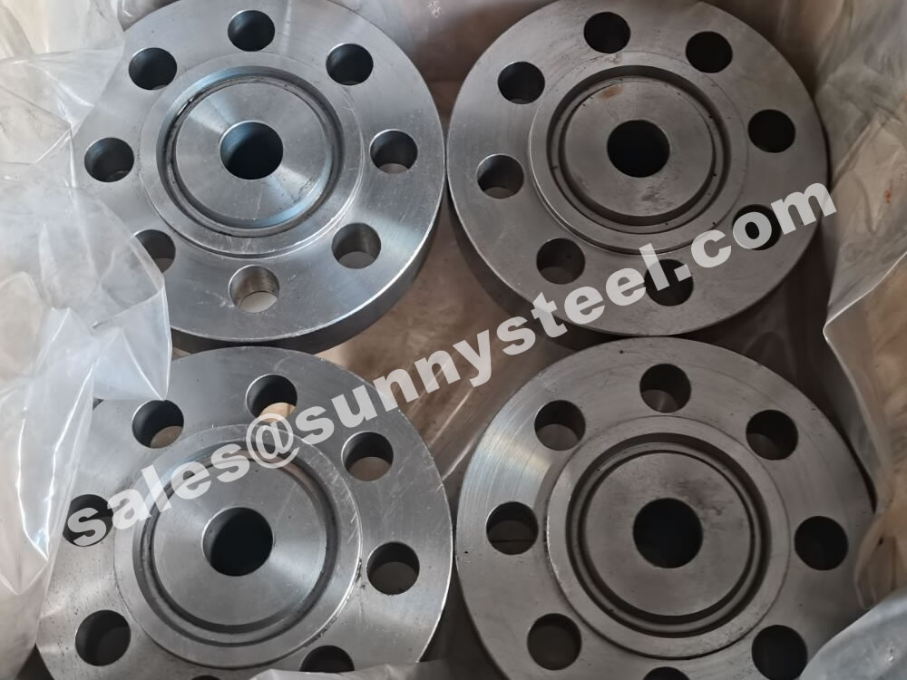
Custom Flanges
A custom flange is manufactured to meet specific customer requirements, such as non-standard dimensions, materials, or finishes.
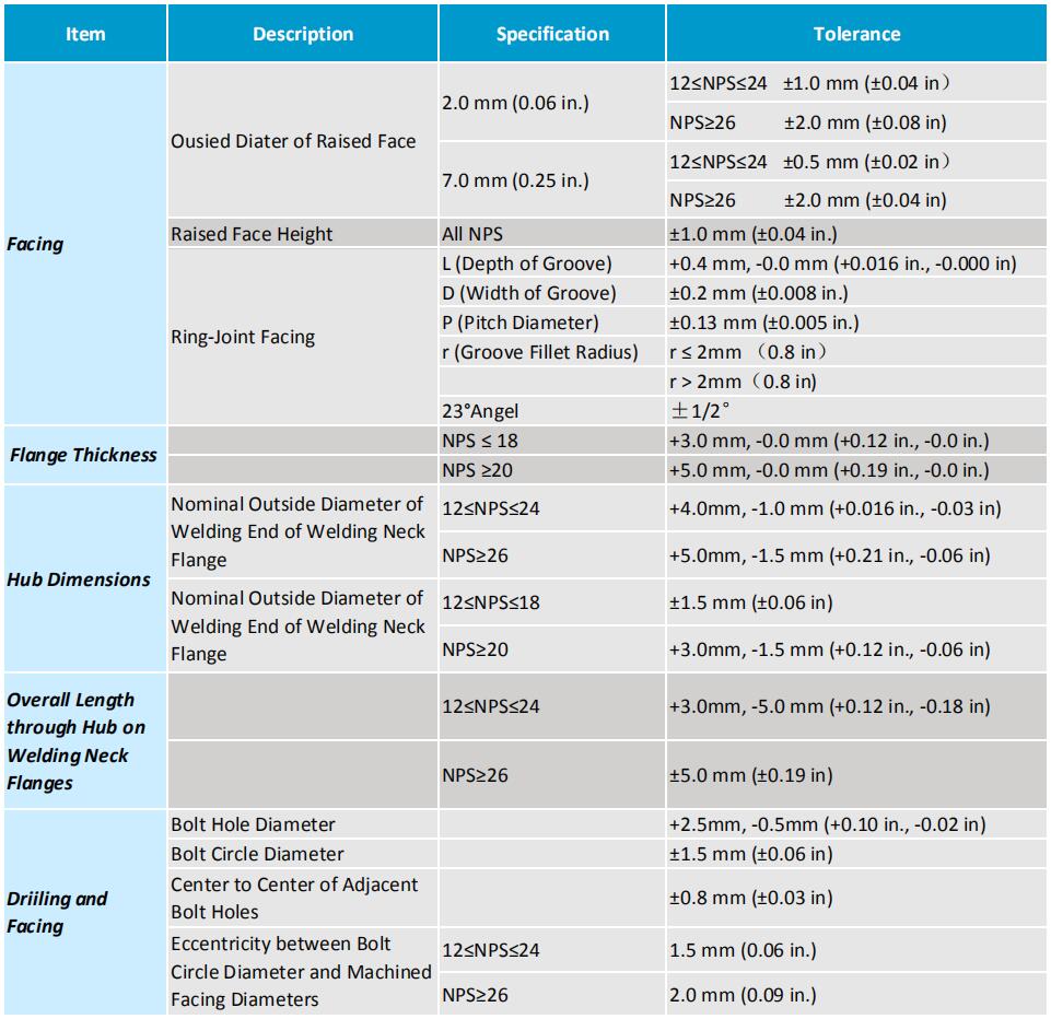
MSS SP-44 refers to the steel pipeline flanges specifications covers pressure-temperature ratings, materials, dimensions, tolerances and testings.
Material Grades from F36, F42, F46, F48, F50, F52, F56, F60, F65, F70, F80, which names from yield strength by 36 ksi (F36) to 80 ksi (F80).
Download PDFMSS SP-44 is the standard for high-strength, cold-worked, carbon steel grade welding for pipelines. It provides guidelines for the design, manufacturing, and testing of flanges used in pipeline systems.
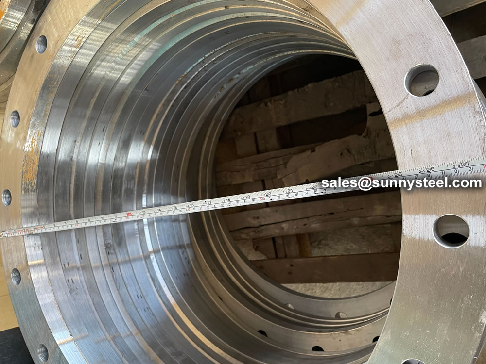
The flanges covered by MSS SP-44 range in size from NPS 12 to NPS 24, and they are equivalent to ASME B16.5 flanges. Additionally, MSS SP-44 also covers flanges larger than NPS 26, which are known as ASME B16.47 Series A flanges.
It is important to note that MSS SP-44 is the only source for NPS 22 flange dimensions.
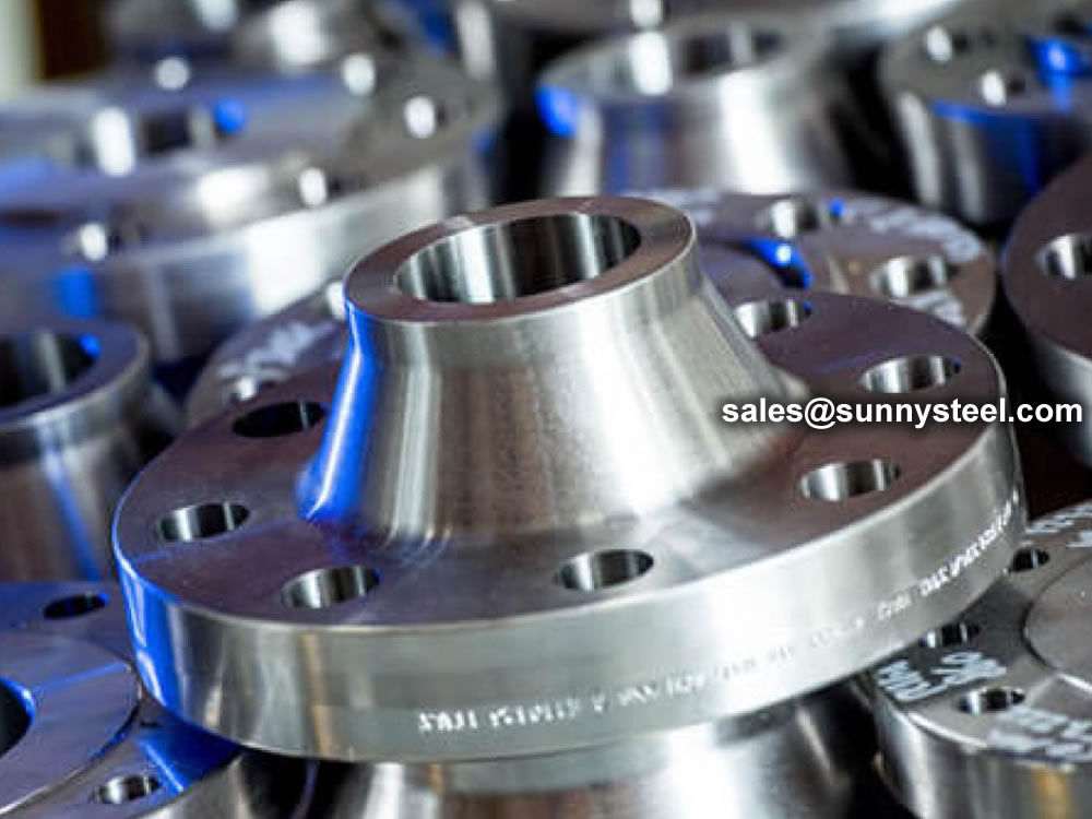
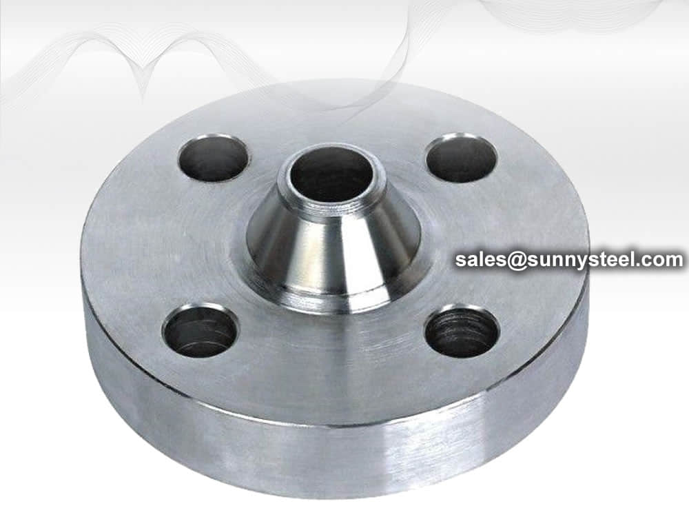
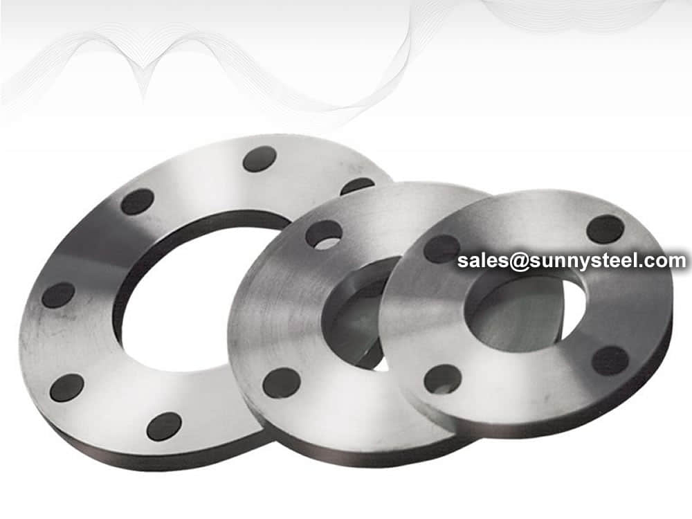
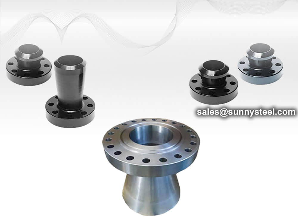
The standard inlcudes all the flange types in forged steel or steel inlcudes Weld Neck Flange, Slip On Flange, Lap Joint Flange and Blind flanges and etc.
Dimensional and tolerance requirements for NPS 10 and smaller flanges in this standard refer to ASME B16.5.
Flanges understand the standard has follwing pressure ratings: Class 150, 300, 400, 600 or 900.
NPS and DN as follows:
| NPS | 12 | 14 | 16 | 18 | 20 | 22 | 24 | 26 | 28 | 30 | 32 | 34 | 36 |
|---|---|---|---|---|---|---|---|---|---|---|---|---|---|
| DN | 300 | 350 | 400 | 450 | 500 | 550 | 600 | 650 | 700 | 750 | 800 | 850 | 900 |
| NPS | 38 | 40 | 42 | 44 | 46 | 48 | 50 | 52 | 54 | 56 | 58 | 60 | � |
| DN | 950 | 1000 | 1050 | 1100 | 1150 | 1200 | 1250 | 1300 | 1350 | 1400 | 1450 | 1500 | � |
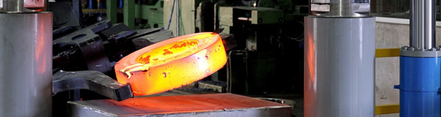
All materials used for making MSS SP-44 flanges shall be "killed" steel. It shall be suitable for field welding to other flanges, fittings, or pipe manufactured according to ASTM A105, A53, A106, A350, A381, A516, A537, A694, A707 and API 5L.
It defines maximum carbon content of 0.30%, and CE shall not exceed 0.48%, based on ladle analysis, without prior approval of the purchaser. If the CE exceeds 0.45%, the flange shal be marked with actual CE result. All test methods shall be as specified in ASTM A370.
Table 1
| Element | Limits (%) | |
|---|---|---|
| Min. | Max. | |
| C | - | 0.3 |
| Mn | 0.6 | 1.6 |
| P | - | 0.025 |
| S | - | 0.025 |
| Si | 0.15 | 0.35 |
| Cu | - | 0.4 |
| Ni | - | 0.4 |
| Cr | - | 0.3 |
| Mo | - | 0.12 |
| V | - | 0.11 |
| Nb | - | 0.05 |
| B | - | 0.001 |
| Cu+Ni+Cr+Mo | - | 1 |
SI (Metric) and U.S. Customary
| Grade | Yield Point (Min.) |
Tensile Strength (Min.) |
Elongation 50mm | ||
|---|---|---|---|---|---|
| Mpa | ksi | Mpa | ksi | (2 in.) (Min. %) | |
| F36 | 248 | 36 | 414 | 60 | 20 |
| F42 | 290 | 42 | 414 | 60 | 20 |
| F46 | 317 | 46 | 414 | 60 | 20 |
| F48 | 331 | 48 | 427 | 62 | 20 |
| F50 | 345 | 50 | 441 | 64 | 20 |
| F52 | 359 | 52 | 455 | 66 | 20 |
| F56 | 386 | 56 | 469 | 68 | 20 |
| F60 | 414 | 60 | 517 | 75 | 20 |
| F65 | 448 | 65 | 531 | 77 | 18 |
| F70 | 483 | 70 | 552 | 80 | 18 |
| F80 | 550 | 80 | 620 | 90 | 16 |
Impact testing is not required for Grade F42 and lower.
From each steel sheet, one set (three specimens) shall be tested at a maximum temperature of -45�?(-50�? and show 27J (20ft-lb) minimum average, 20J (15 ft-lb) individual minium.
Hardness shall be HBW 235 as maximum.
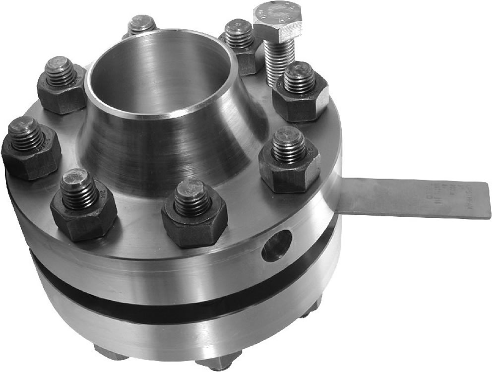
Boltings listed in Table 3 shall be used in flanged joints covered by MSS SP-44. Bolting produced from other materials may be used if permitted by the applicable code or governmental regulation.
MSS SP-42 F42 and higher grades shall be normalized, normalized and tempered, quenched and tempered, or precipitation treated and aged. Class 400 and higher classes of Grade F36 flanges shall be anneald, normalized, normalized and tempered, or quenched and tempered as defined in ASTM A961; But the minimum tempering temperature shall be 540�?(1000�?.
The flange drilling template is determined as follows:
The Class 150 flange drilling template is identical to the Class 125 in ASME B16.5 and ASME B16.1.
The drilled template for class 300 flanges smaller than or equal to NPS24 is the same as that for class 250 flanges in ASME B16.5 and ASME B16.1. The drilled templates for class 400, class 600, and class 900 flanges in sizes less than or equal to NPS24 are the same as those for ASME B16.5.
The NPS 26 through NPS 60 Class 150, 300, 400, 600, and 900 flanges are the same as those of series A flanges in ASME standard B16.47.
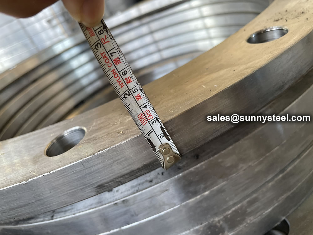
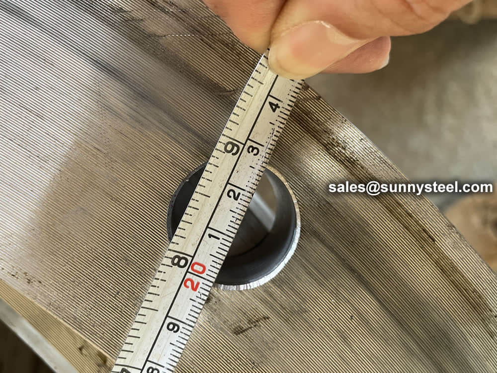
For flanges with nominal pipe diameter less than or equal to NPS24, the outer diameter and flange thickness shall meet the requirements of ASME B16.5. For flanges with nominal pipe diameters of NPS26 through NPS60, the outer diameter and flange thickness shall comply with the requirements of ASME B16.47 for series A flanges
ASME B16.5 and B16.47 weld flange ratings are based on the weld flange neck and have a calculated wall thickness at least equal to the pipe. The pipe has a specified minimum yield strength of 276 MPa (40000 psi) and a maximum bore size.
When the mechanical properties (minimum yield strength) of the various parts are equal to or greater than the line to which it is connected, the flange neck may be the same size as specified in the ASME B16.5 or 16.47A series.
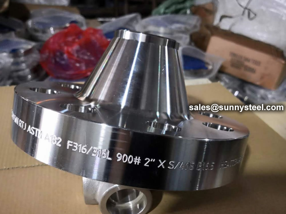
Flanges shall be marked in accordance with the rules specified in MSS Standard Practice SP-25. In addition, the letter PL should be added before the level symbol. The grade symbol on the weld neck flange marks the material grade of the weld flange neck.
The accuracy of the pipe flange contact surface should be determined by the visual comparison method using the Ra sample block instead of the stylus plotter and the electronic magnifier.
It provide concentric serrated or helical teeth with an accuracy between 3.2 μm (125 μinch) and 6.3μm (250μinch). The cutting tool used shall have a radius greater than or equal to 1.5mm (0.06 in) and 1.7 to 2.2 grooves per mm (44 to 55 grooves per inch).
The side surface roughness of gasket groove shall not exceed 1.6μm �?3μinch�?
Hydrostatic test of the flange is not required. However, the hydrostatic pressure test of the flange joint may be carried out at a pressure not exceeding 1.5 times the 38 ° C (100 ° F) rating.
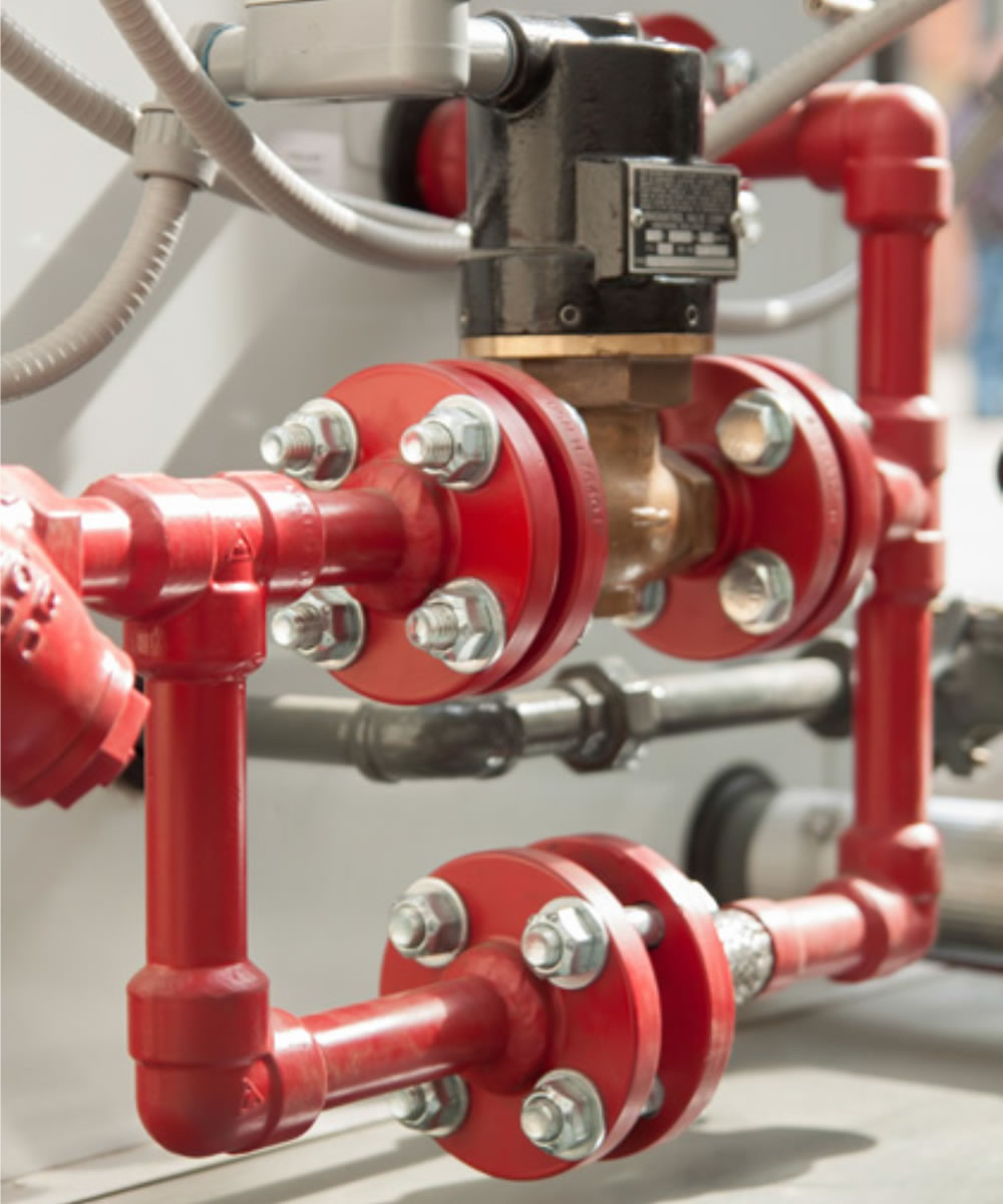
A flange is a method of connecting pipes, valves, pumps, and other equipment to form a piping system. It also provides easy access for cleaning, inspection, or modification.
When a piping joint requires to be dismantled, flanges are being used. These are primarily used on equipment, valves, and specialty items. Breakout flanges are provided at predetermined intervals in certain pipelines where maintenance is a regular occurrence. The flanges, gaskets, and bolting make up a flanged joint, which is made up of three separate but interconnected components. To achieve a leak-proof joint, special controls are required in the selection and application of all of these elements.
Here are the details of Flanges about their advantages and their applications.
Pipes, valves, pumps, and other parts are connected with flanges to form a piping system. Generally, flanges are welded or screwed together. The use of flanges makes pipe system maintenance and repair a breeze. Instead of taking the entire pipe for inspection, a small section of the pipe can be carefully investigated to use a flange to locate the fault.
The following are the five most important benefits of The following are the five most important benefits of flanges:
A flange is a method of connecting pipes, valves, pumps, and other equipment to form a piping system. It also provides easy access for cleaning, inspection, or modification. Flanges are usually welded or screwed.
In many applications, engineers need to find a way to close off a chamber or cylinder in a very secure fashion, usually because the substance inside must differ from the substance outside in composition or pressure.
They do this by fastening two pieces of metal or other material together with a circle of bolts on a lip. This “lip” is a flange.
You can connect two sections of metal piping by soldering or welding them together, but pipes connected in this way are very susceptible to bursting at high pressures. A way of connecting two sections of pipe more securely is by having flanged ends that you can connect with bolts. This way, even if gases or liquids build up to high pressures inside the pipe, it will often hold with no problem.
In order to connect two sections of a large, enclosed area, it is often best to used flanges and bolts. An example of this is the connection between the engine and the transmission in an automobile. In this case, both the engine and the transmission contain a number of moving parts that can easily get damaged if they get dust or other small objects inside of them. By connecting the outer casings of the engine and transmission in this way, engineers protect the inner workings of both.
Flanges have a specific purpose in cameras and other electronic devices. Though flanges in such items do not usually have to sustain high pressures, they do have to hold tight so they can keep out harmful particles. These flanges are usually found connecting two different materials, such as the glass of a lens and the rest of the body of the camera.
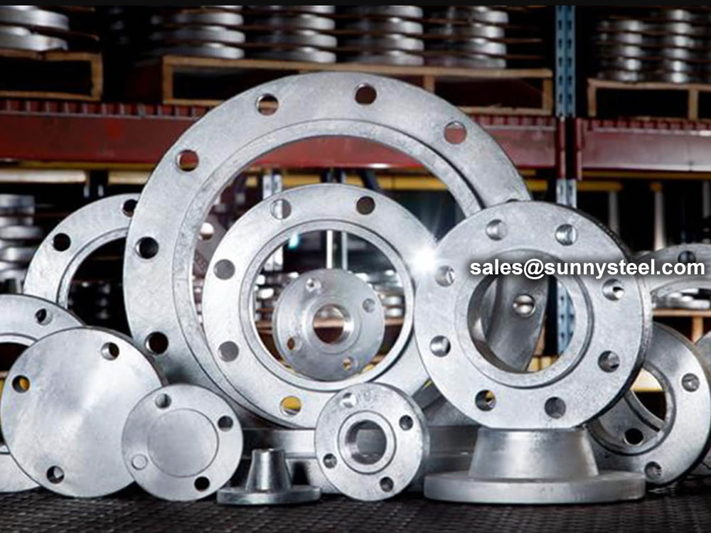
Pipe flanges are manufactured in all the different materials like stainless steel, cast iron, aluminium, brass, bronze, plastic etc. but the most used material is forged carbon steel and have machined surfaces.
Flanges are welded to pipe and equipment nozzle. Accordingly, it is manufactured from the following materials;
The list of materials used in manufacturing is covered in ASME B16.5 & B16.47.
Commonly used Forged material grads are
| Material | Fittings | Flanges | Valves | Bolts & Nuts |
|---|---|---|---|---|
| Carbon Steel | A234 Gr WPA | A105 | A216 Gr WCB | A193 Gr B7 A194 Gr 2H |
| A234 Gr WPB | A105 | A216 Gr WCB | ||
| A234 Gr WPC | A105 | A216 Gr WCB | ||
| Carbon Steel Alloy High-Temp |
A234 Gr WP1 | A182 Gr F1 | A217 Gr WC1 | A193 Gr B7 A194 Gr 2H |
| A234 Gr WP11 | A182 Gr F11 | A217 Gr WC6 | ||
| A234 Gr WP12 | A182 Gr F12 | A217 Gr WC6 | ||
| A234 Gr WP22 | A182 Gr F22 | A217 Gr WC9 | ||
| A234 Gr WP5 | A182 Gr F5 | A217 Gr C5 | ||
| A234 Gr WP9 | A182 Gr F9 | A217 Gr C12 | ||
| Carbon Steel Alloy Low-Temp |
A420 Gr WPL6 | A350 Gr LF2 | A352 Gr LCB | A320 Gr L7 A194 Gr 7 |
| A420 Gr WPL3 | A350 Gr LF3 | A352 Gr LC3 | ||
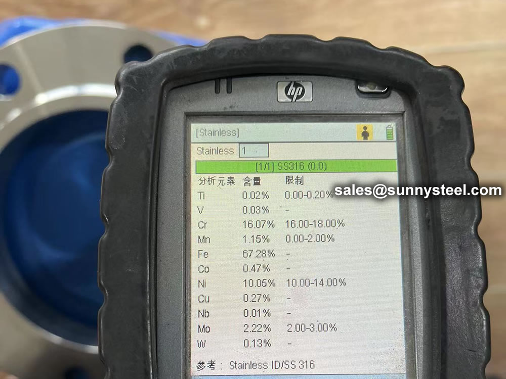
| Austenitic Stainless Steel | A403 Gr WP304 | A182 Gr F304 | A182 Gr F304 | A193 Gr B8 A194 Gr 8 |
| A403 Gr WP316 | A182 Gr F316 | A182 Gr F316 | ||
| A403 Gr WP321 | A182 Gr F321 | A182 Gr F321 | ||
| A403 Gr WP347 | A182 Gr F347 | A182 Gr F347 |
ASTM standards define the specific manufacturing process of the material and determine the exact chemical composition of pipes, fittings and flanges, through percentages of the permitted quantities of carbon, magnesium, nickel, etc., and are indicated by "Grade".
The usual materials of flanges include stainless steel, carbon steel, aluminum and plastic. The choice of the material largely depends on the purpose of the flange. For example, stainless steel is more durable and is necessary for heavy use. On the other hand, plastic is more feasible for use in the home because of its reasonable price and easy installation. The materials used for flanges are under the designation of the American Society of Mechanical Engineers.
The most common materials for pipe flanges (forged grades) are: ASTM A105 (carbon steel high temperature to match A53/A106/API 5L pipes), A350 Grades LF1/2/3 (carbon steel low temperature to match A333 pipes), A694 Grades F42 to F80 (high yield carbon steel to match API 5L pipe grades), ASTM A182 Grades F5 to F91 (alloy steel flanges to match A335 pipes), A182 Grade F304/316 (stainless steel flanges to match A312 SS pipes), A182 Gr. F44/F51/F53/F55 (duplex and super duplex to match A790/A928 pipes) and various nickel alloy grades (Inconel, Incoloy, Hastelloy, Monel).
The material qualities for these flanges are defined in the ASTM standards.
For example, a carbon steel pipe can be identified with Grade A or B, a stainless-steel pipe with Grade TP304 or Grade TP321, a carbon steel fitting with Grade WPB etc.


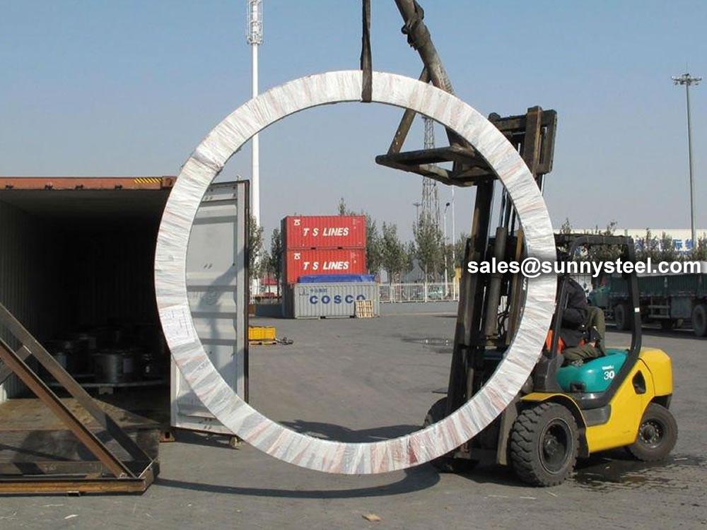
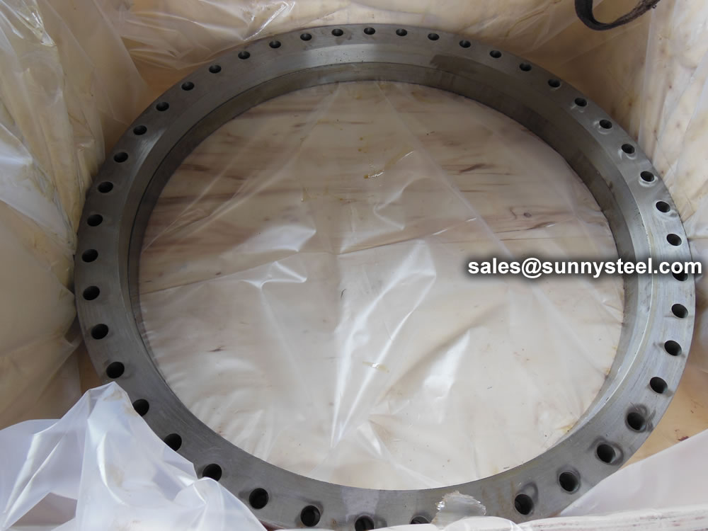
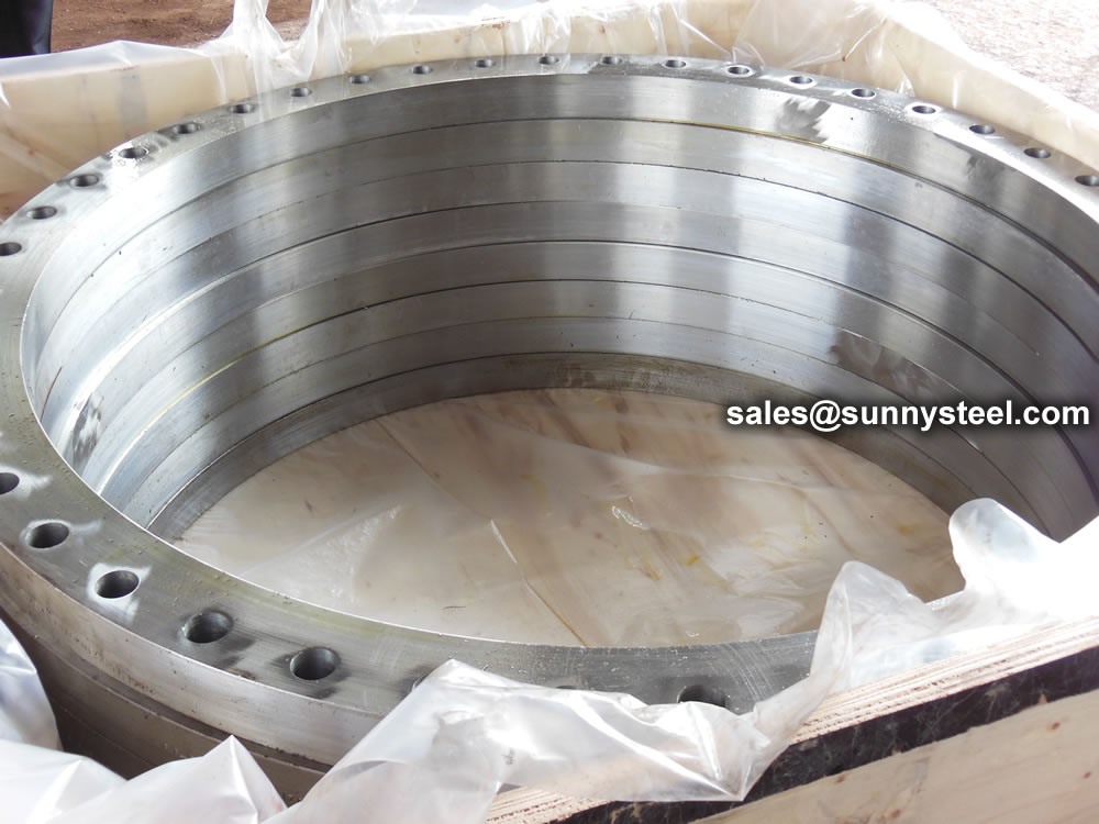
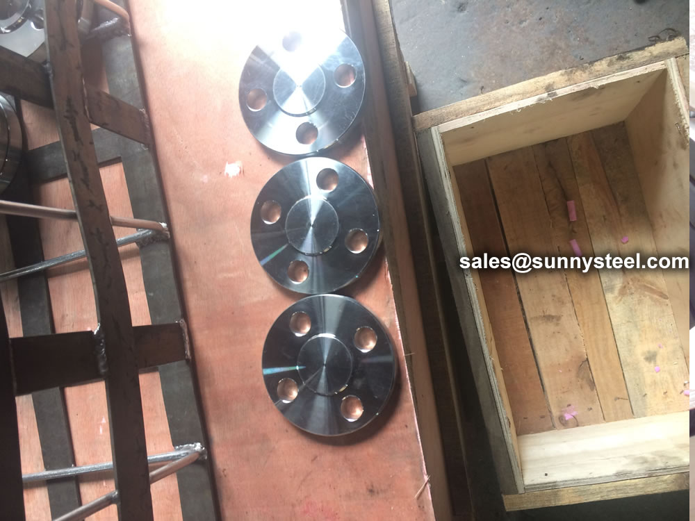
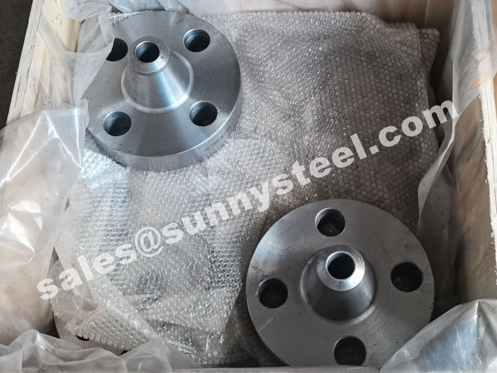
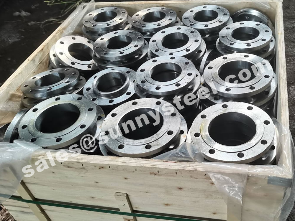
Steel flanges must be packed with seaworthy packing method then delivery to customers, usually the packing way include wooden box, wooden pallet, iron & steel cage, iron & steel pallet etc.
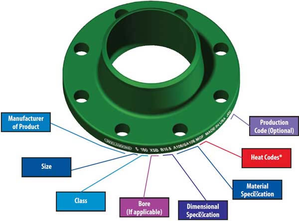
Flange markings are governed by ANSI ASME codes. Flange marking includes;

ASME B16.5 and B16.47 standards cover permissible tolerances for inspection.
Because of the normal wooden boxes or wooden pallets have to do fumigation treatment, we usually use plywood pallet or plywood case or box to pack steel flanges without fumigation treatment.

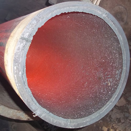
Ceramic lined pipe is made through self-propagating high-temperature synthesis (SHS) technique.
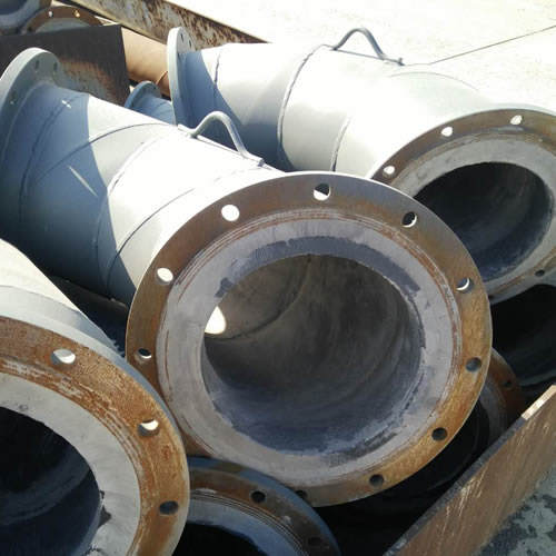
Cast basalt lined steel pipe is composed by lined with cast basalt pipe, outside steel pipe and cement mortar filling between the two layers.
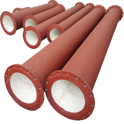
Ceramic tile lined pipes have very uniform coating of specially formulated ceramic material that is affixed to the inner of the pipe.
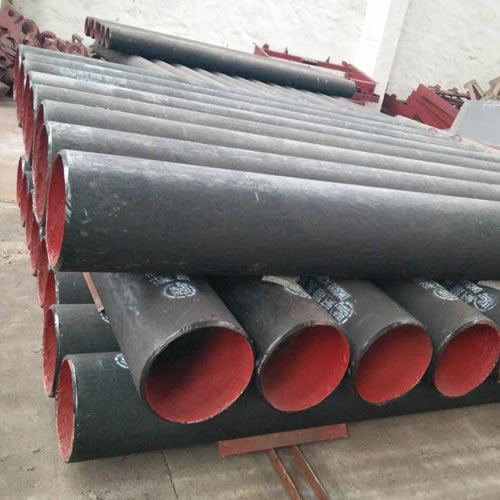
The material of the rare earth alloy wear-resistant pipe is ZG40CrMnMoNiSiRe, which is also the grade of rare earth alloy steel.
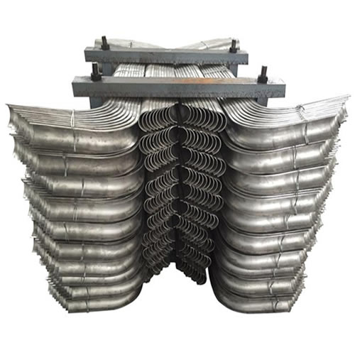
Tubes Erosion Shields are used to protect boiler tubing from the highly erosive effects of high temperatures and pressures thereby greatly extending tube life.
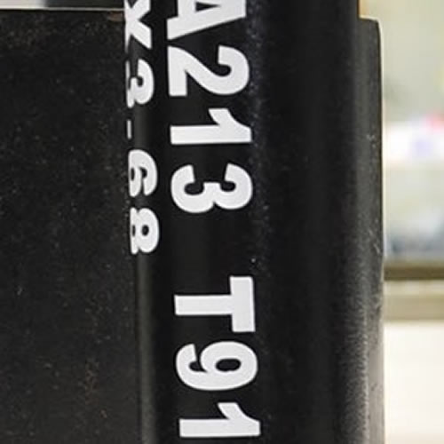
The ASTM A213 T91 seamless tubes are primarily used for boiler, superheater, and heat-exchanger.

When you partner with Sunny Steel, you can stop worrying about meeting deadlines thanks to our responsive and timely service. You'll also say goodbye to unnecessary shopping around. Instead, you'll get white glove service from an expert who understands your needs and can get you the materials you need quickly.