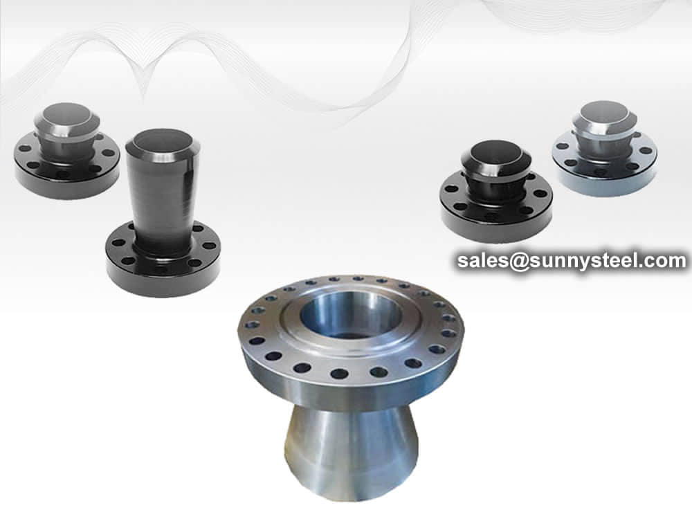
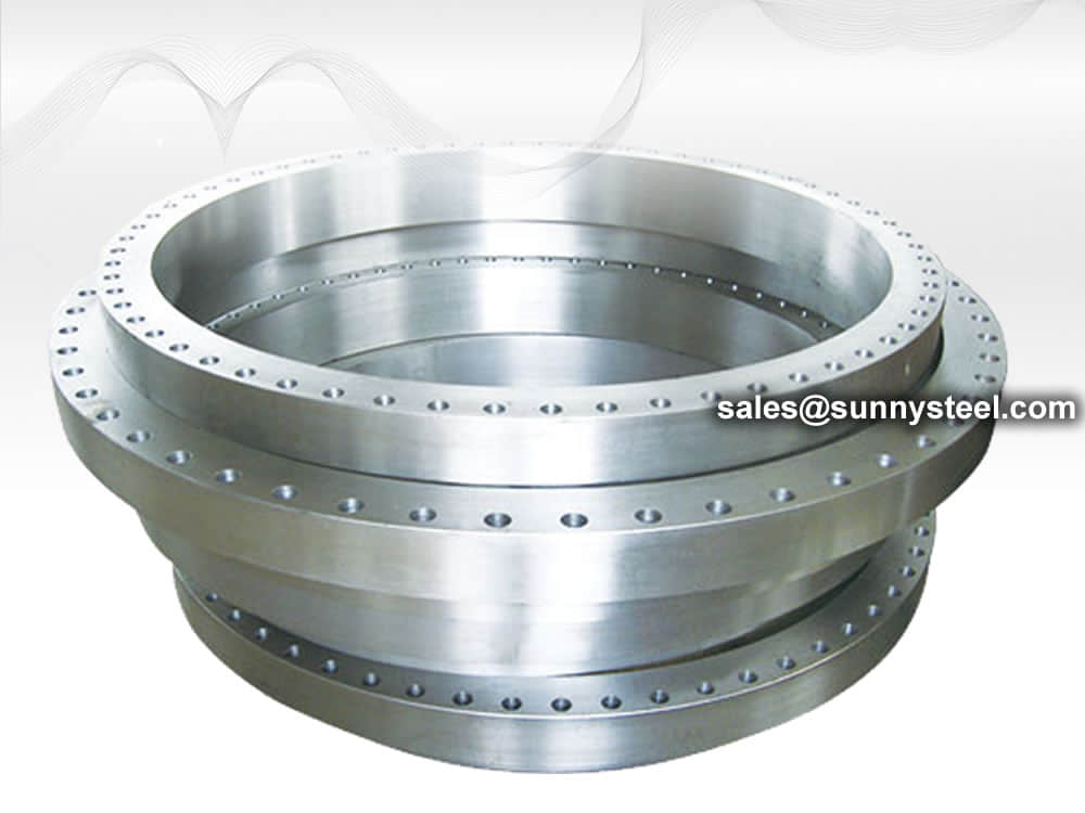
Custom Flanges
A custom flange is manufactured to meet specific customer requirements, such as non-standard dimensions, materials, or finishes.
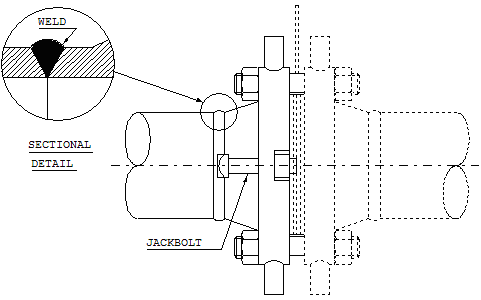
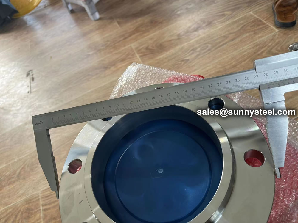
Orifice flange for run installation should be so constructed, machined and attached to the that the inner surface of the passage extends through the orifice flange so that there is no recess at the orifice plate.
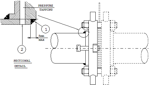
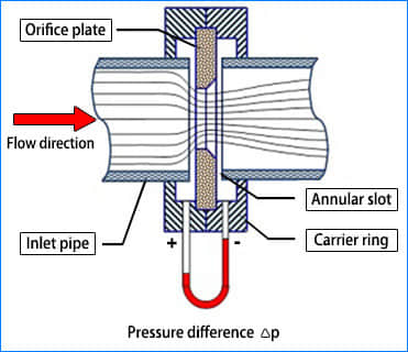
An orifice flange is used to measure the flow of the fluid conveyed by the pipeline via a flow nozzle positioned on the flange itself. Pairs of pressure tappings are machined onto the orifice flange, making separate tappings on the pipe wall unnecessary.
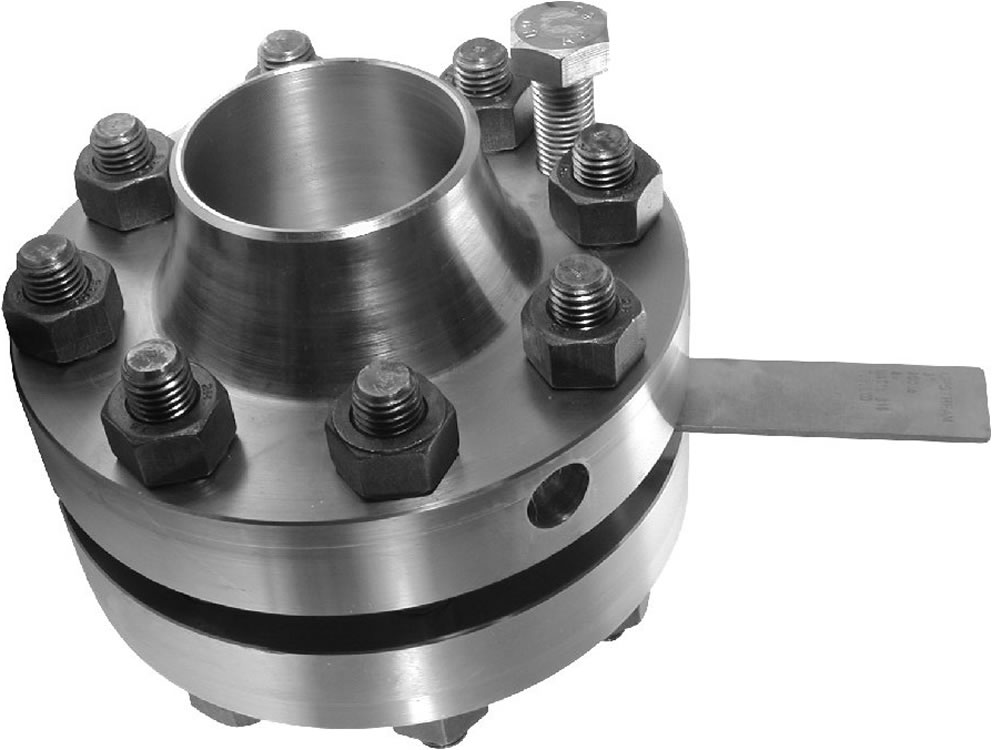
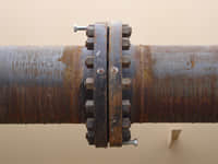
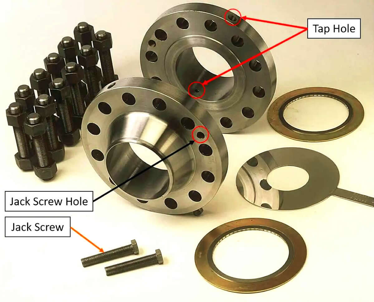
The traditional orifice flange assembly consists of a pair of flanges, orifice plate, bolts, nuts, gaskets, jacking screws and plugs. Jacking screws ensure the easy removal of the primary flow element.
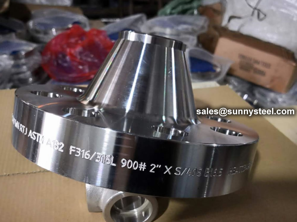
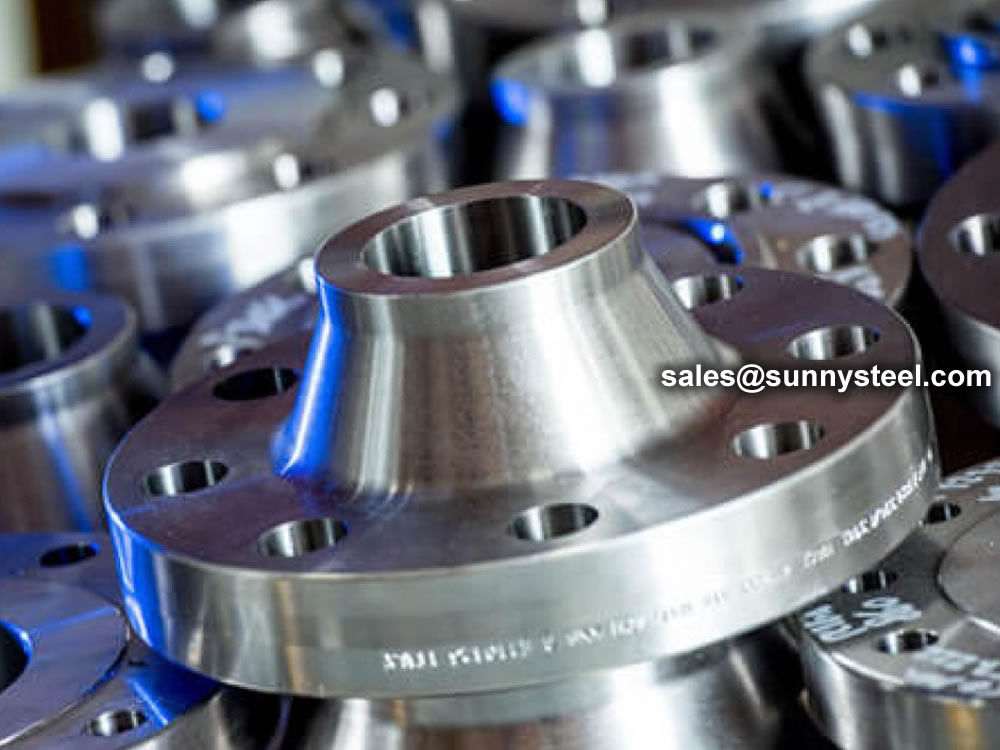
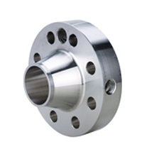
Orifice flanges are available in all ASTM forged grades (ASTM A105, ASTM A350, ASTM A694, ASTM 182 respectively for carbon, alloy and, stainless steel flanges), dimensions (combinations of nominal sizes and pressure ratings) and, in socket weld, threaded or weld neck shape (WN is the most used).
Orifice flange for run installation should be so constructed, machined and attached to the that the inner surface of the passage extends through the orifice flange so that there is no recess at the orifice plate.
Orifice flanges are used instead of the standard pipe flanges when orifice plate or flow nozzle is used. The basic purpose for this is to measuring the flow rate of either gases or liquids in the respective pipeline.
These flanges are used in various industrial applications and are available in various sizes and materials.
An Orifice Flange is used in combination with orifice meters to measure the flow rate of oil, gas, and other liquids conveyed by the pipeline.
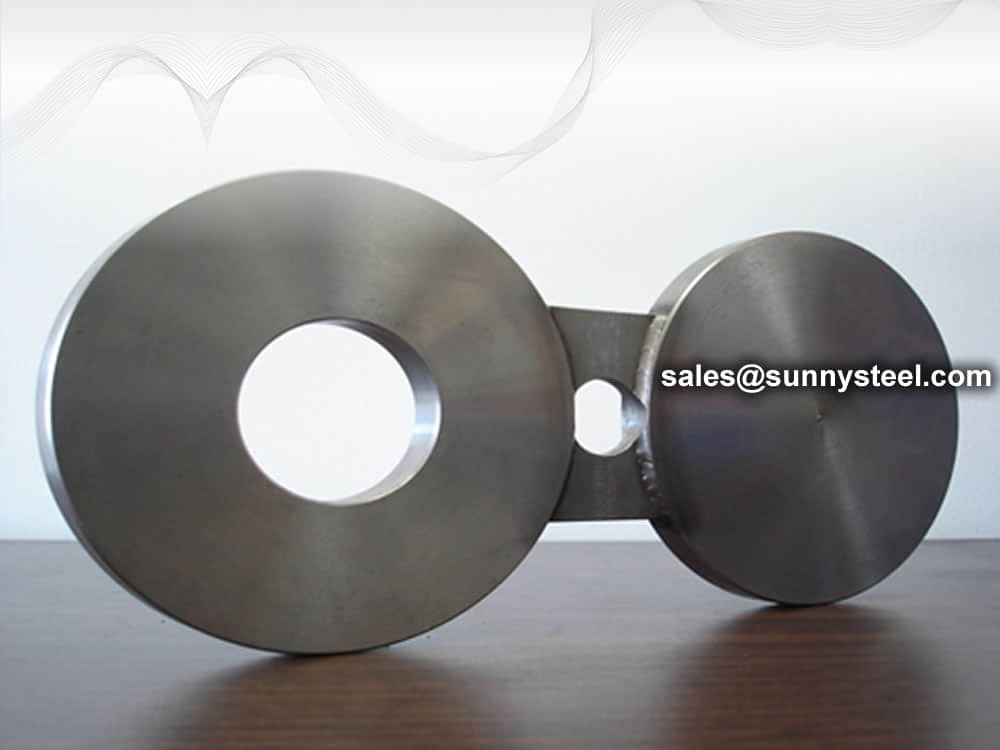
An orifice flange is a type of flange assembly used to measure the flow of products, such as liquids, steam, or gases, through a piping system. It consists of a pair of flanges, bolts, nuts, gaskets, jack screws, and plugs The orifice plate, which is a thin plate with a center bore, is installed in the orifice flange to create a restriction of flow, resulting in a differential pressure that can be used to measure the flow rate.
Orifice flanges are typically installed in a straight run of pipe to avoid turbulence at the orifice plate. According to the American Gas Association, there should be ten pipe diameters upstream of the orifice plate and five diameters downstream.
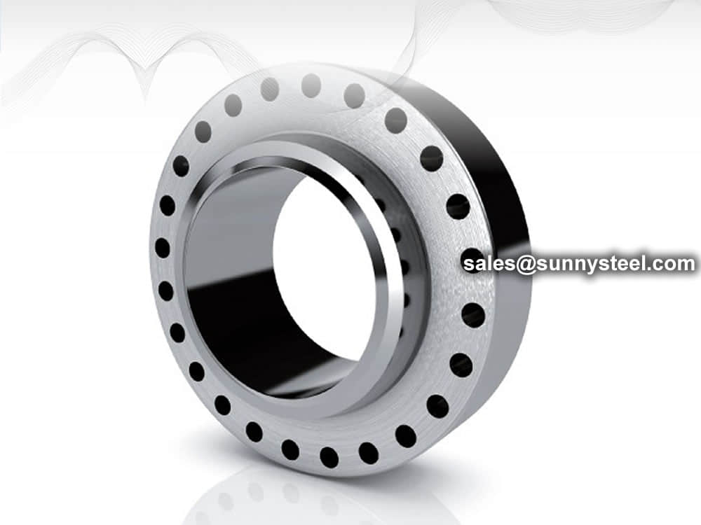
The orifice flange sets are available in various sizes and pressure classes, and they are primarily supplied as raised face weld neck flanges. Other flange facings and types can be supplied upon request to meet specific needs and requirements.
The orifice flange assemblies are designed to ensure accurate centralization of the orifice bore to the flange bore, following the requirements of standards such as ASME MFC-3M, ASME MFC-14M, AGA 3, and ISO 5167-2.
Orifice flanges are commonly used with orifice meters to measure the flow rate of liquids or gases in a pipeline. They are manufactured with high-quality materials and comply with applicable industry standards.
Orifice flanges are available in all ASTM forged grades (ASTM A105, ASTM A350, ASTM A694, ASTM 182 respectively for carbon, alloy and, stainless steel flanges), dimensions (combinations of nominal sizes and pressure ratings) and, in socket weld, threaded or weld neck shape (WN is the most used).
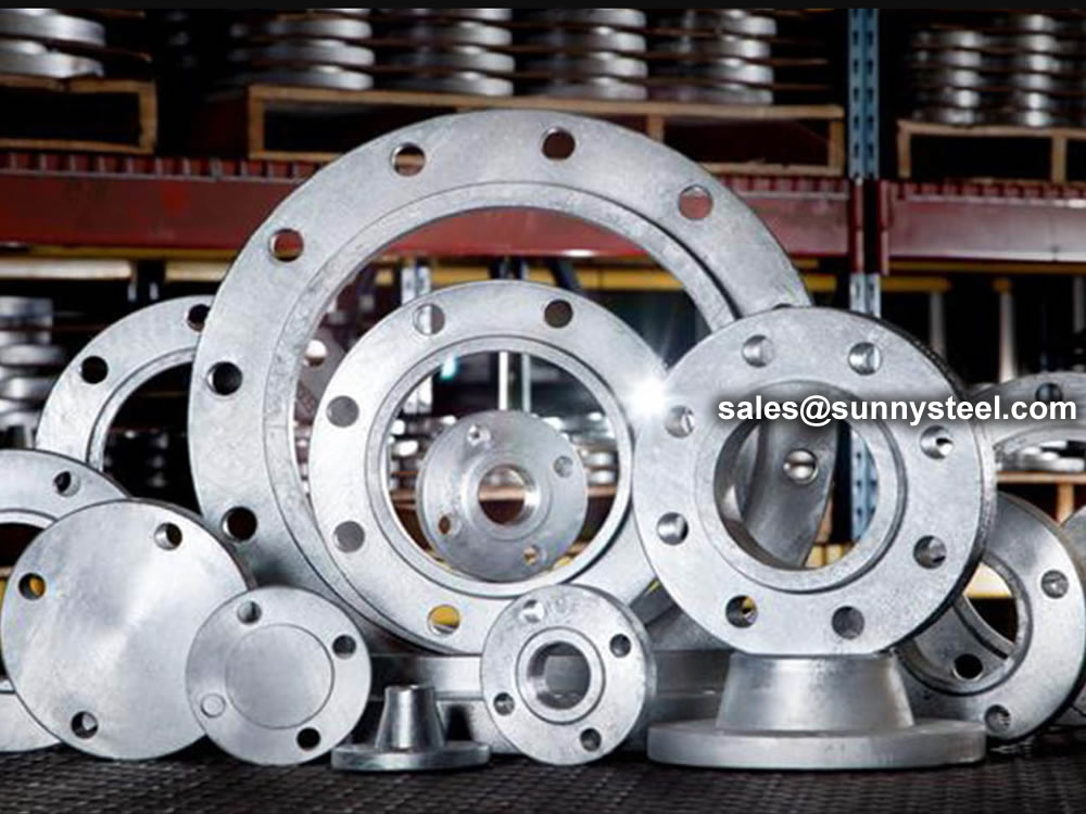
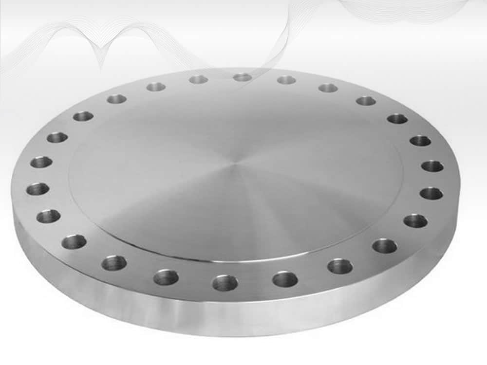
Orifice Flange manufacturer Sunny Steel supplies Orifice Flanges, Plate Flanges,
Orifice flanges, abbreviated as ORFF, are for metering the volumetric flow rate of liquids and gasses through a pipe. Two orifice flanges are called an orifice flange union. Each flange comes with two pipe taps for measuring the pressure drop of the flow through an orifice plate. Orifice plates do not come with the flanges and are sized based on the requirements of the process. Two jack screws are used to spread the flanges apart in order to change the orifice plate. This flange is normally available in weld neck, slip-on, and threaded flanges. These flanges have a raised face.
Orifice flanges are installed in a straight run of pipe in order to avoid turbulence at the plate. As a rule of thumb, an orifice flange has ten diameters of straight pipe upstream and five diameters of pipe downstream. There are guidelines set out in (American Gas Association) AGA Report #3 which is the Orifice Metering of Natural gas.
When installing the orifice plate flange the pressure taps need to be at the same elevation to each other. The assumption when making the calculation for the orifice plate is that static head of the tubes is the same on both sides of the orifice plate. Pressure taps should not be installed facing down as the taps could become plugged with debris in the line.
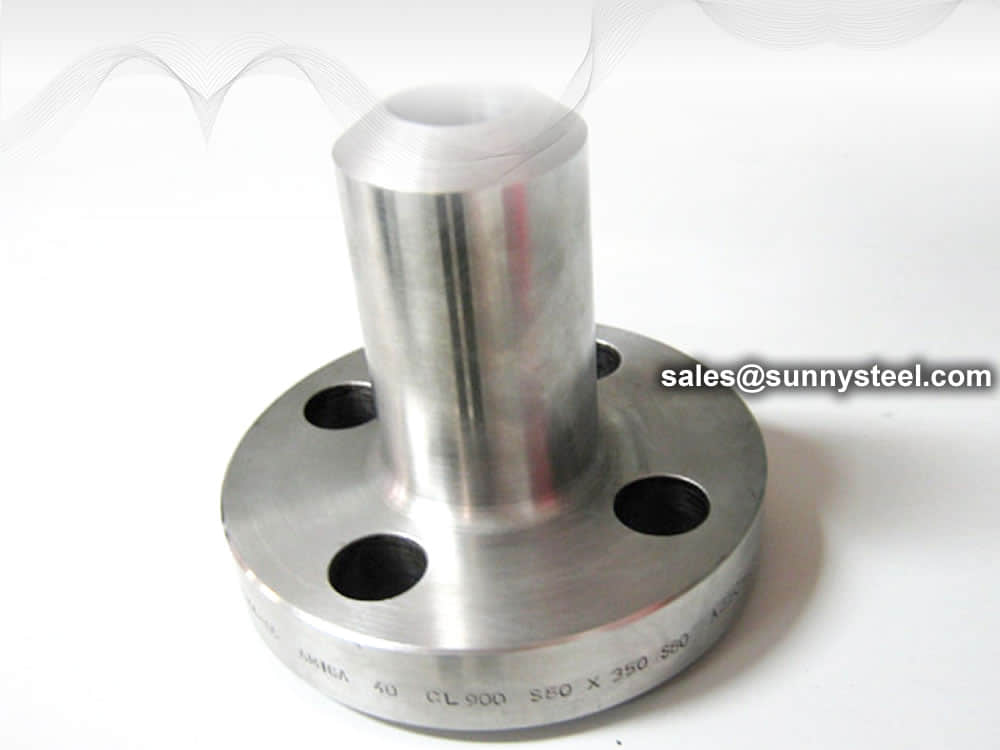
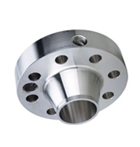
Weldneck orifice flanges are butt-welded into the pipeline. The inside diameter (bore diameter) of the pipe should be specified when ordering. Weldneck orifice flanges are available in ANSI classes 300, 600, 900, 1500 and 2500. They are not available in ANSI 150 sizes because the thickness of ANSI 150 flanges are not enough to allow for drilling pressure taps.
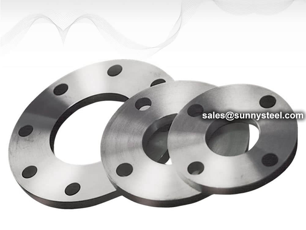
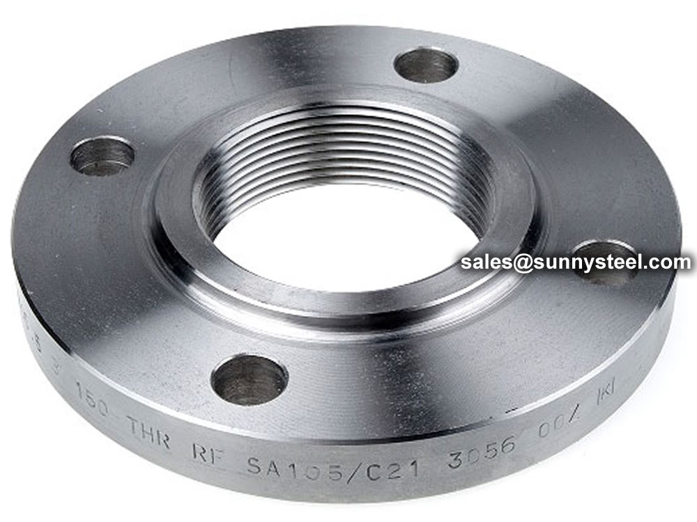
The range of orifice flanges covers all standard sizes and ranges, and all common flange materials. Flanges are available in Welding Neck, Slip On, and Threaded form, and are typically supplied with two 1/2″ NPT tappings in each flange.
ASME B16.36 covers Dimensions and dimensional tolerances from orifice flanges (similar to those covered in ASME B16.5) that have orifice pressure differential connections.
The range of orifice flanges covers all standard sizes and ranges, and all common flange materials. Flanges are available in Welding Neck, Slip On, and Threaded form, and are typically supplied with two 1/2″ NPT tappings in each flange.
NPT is the best known and most widely used connection where the pipe thread provides both the mechanical joint and the hydraulic seal.
ASME B1.20.1 covers dimensions and gaging of NPT pipe threads for general purpose applications.
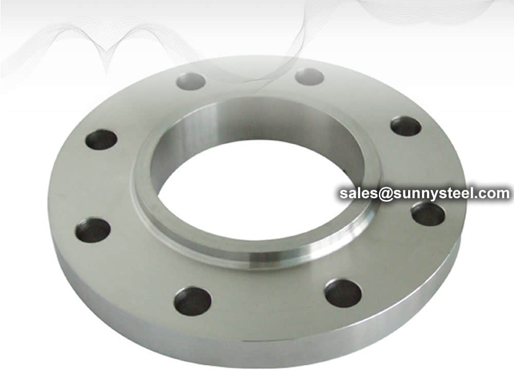
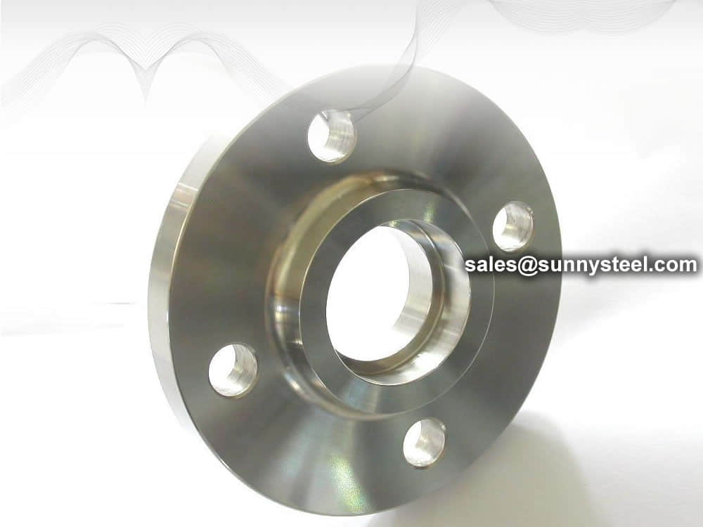
Orifice Flanges generally come with either Raised Faces or RTJ (Ring Type Joint) facings. They are, for all intensive purposes, the same as weld neck and slip on flanges with extra machining.
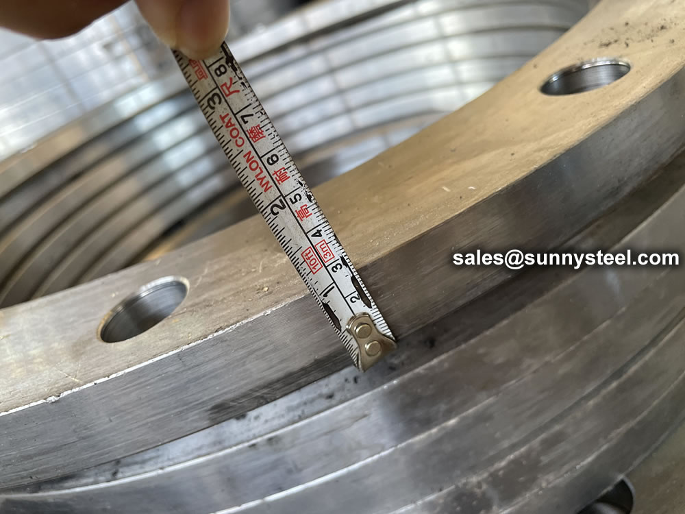
Orifice flange for run installation should be so constructed, machined and attached to the that the inner surface of the passage extends through the orifice flange so that there is no recess at the orifice plate.
The flange bore and the section of pipe shall be of the same internal diameter.
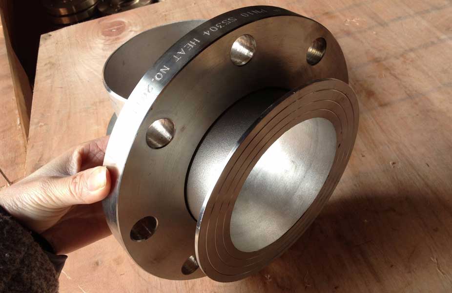
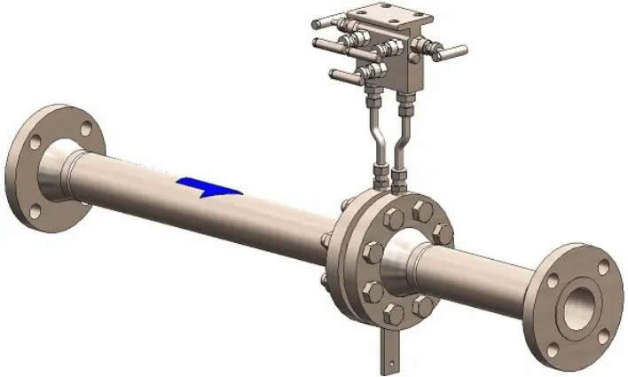
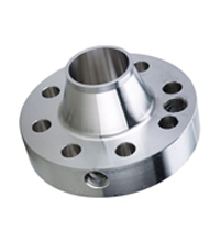
Weldneck and Slip-On Orifice Runs
Weld Neck Orifice Run
Two Orifice Flanges are called an orifice flange union. Each flange comes with two pipe taps for measuring the pressure drop of the flow through an orifice plate.. Orifice plates do not come with the flanges and are sized based on the requirements of the process. Two jack screws are used to spread the flanges apart in order to change the orifice plate. This flange is normally available in weld neck, slip-on, and threaded flanges.
These flanges have a raised face.
Orifice flanges are installed in a straight run of pipe in order to avoid turbulence at the plate. As a rule of thumb, an orifice flange has ten diameters of straight pipe upstream and five diameters of pipe downstream.
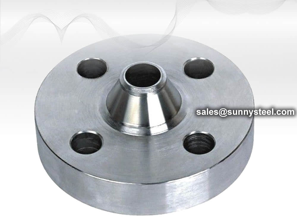
An Orifice Flange is intended for use instead of standard pipe flanges when an orifice plate or flow nozzle must be installed. Pairs of pressure tapings are machined into the Orifice Flange, making separate orifice carriers or tapings in the pipe wall unnecessary. This type of flange includes the orifice plate with data tap, a pair of flanges with integrated taps, a set of gaskets, bolts and nuts and a jackscrew to assist separating the flanges for orifice inspection.
Design can be with RF or RTJ weld neck flanges or RF slip-on flanges. The orifice plates are centered within very close tolerances of the standards.
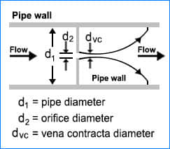
An Orifice plate is a device used for measuring flow rate. Either a volumetric or mass flow rate may be determined, depending on the calculation associated with the orifice plate. It uses the Bernoulli’s principle which states that there is a relationship between the pressure of the fluid and the velocity of the fluid. When the velocity increases, the pressure decreases and vice versa.
An Orifice plate is a thin plate with a hole in the middle. It is usually placed in a pipe in which fluid flows. When the fluid reaches the orifice plate, the fluid is forced to converge to go through the small hole; the point of maximum convergence actually occurs shortly downstream of the physical orifice, at the so-called vena contracta point As it does so, the velocity and the pressure changes. Beyond the vena contracta, the fluid expands and the velocity and pressure change once again. By measuring the difference in fluid pressure between the normal pipe section and at the vena contracta, the volumetric and mass flow rates can be obtained from Bernoulli’s equation.
When installing the orifice plate flange the pressure taps need to be at the same elevation to each other. The assumption when making the calculation for the orifice plate is that static head of the tubes is the same on both sides of the orifice plate. Pressure taps should not be installed facing down as the taps could become plugged with debris in the line.
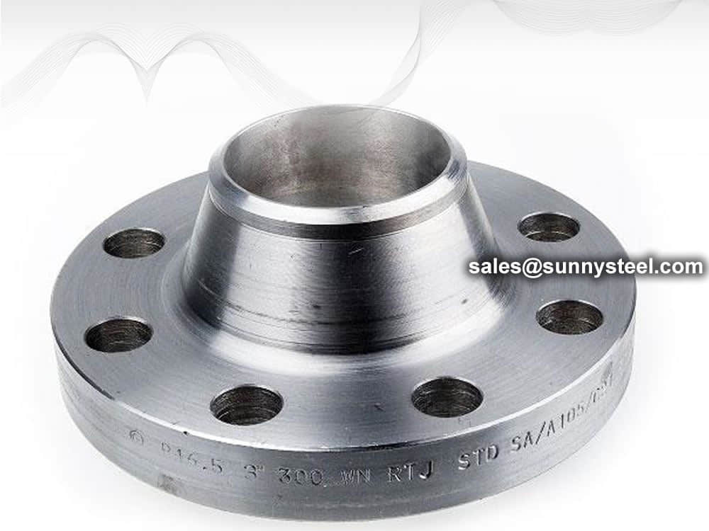
Weld Neck Orifice Flanges are butt-welded into the pipeline. The inside diameter (bore diameter) of the pipe should be specified when ordering. Weldneck orifice flanges are available in ANSI classes 300, 600, 900, 1500 and 2500. They are not available in ANSI 150 sizes because the thickness of ANSI 150 flanges are not enough to allow for drilling pressure taps.
Orifice flanges are installed in a straight run of pipe in order to avoid turbulence at the plate. As a rule of thumb, an orifice flange has ten diameters of straight pipe upstream and five diameters of pipe downstream.
Union
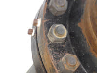
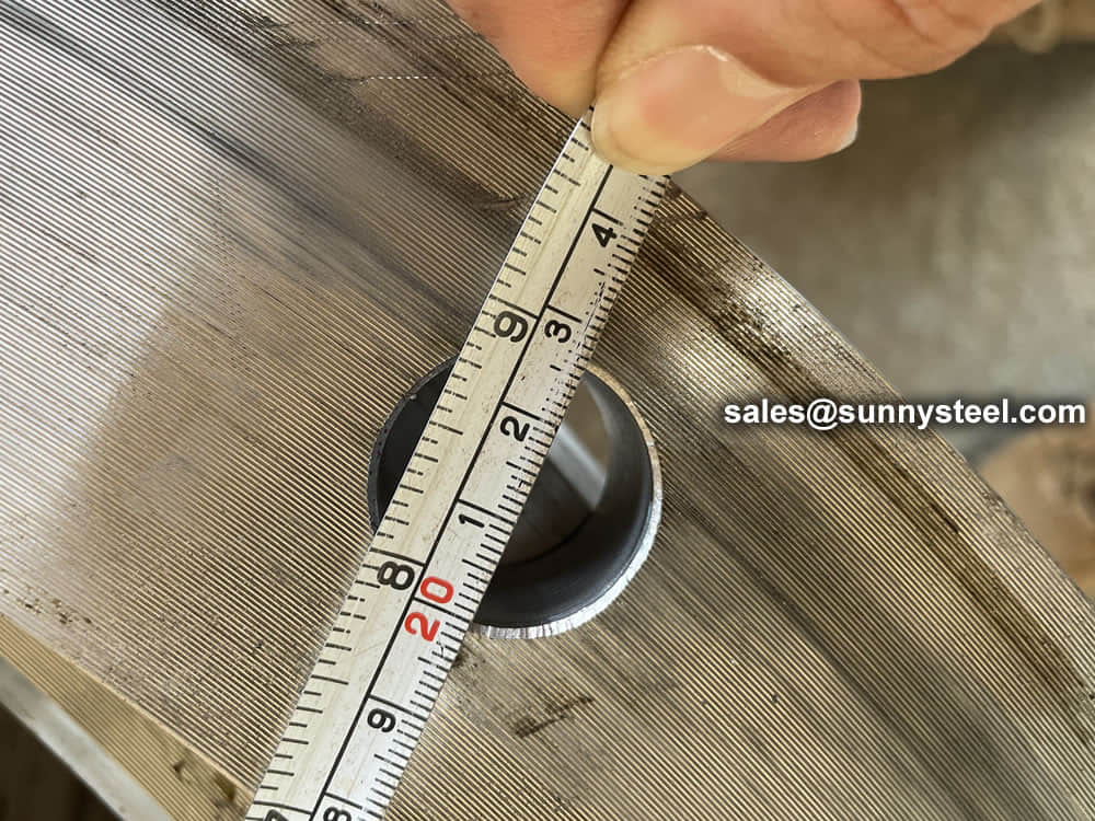
Pipe tap
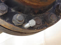
Jack screw
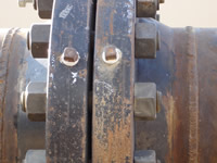
Pipe taps
When installing the orifice plate flange the pressure taps need to be at the same elevation to each other. The assumption when making the calculation for the orifice plate is that static head of the tubes is the same on both sides of the orifice plate. Pressure taps should not be installed facing down as the taps could become plugged with debris in the line.
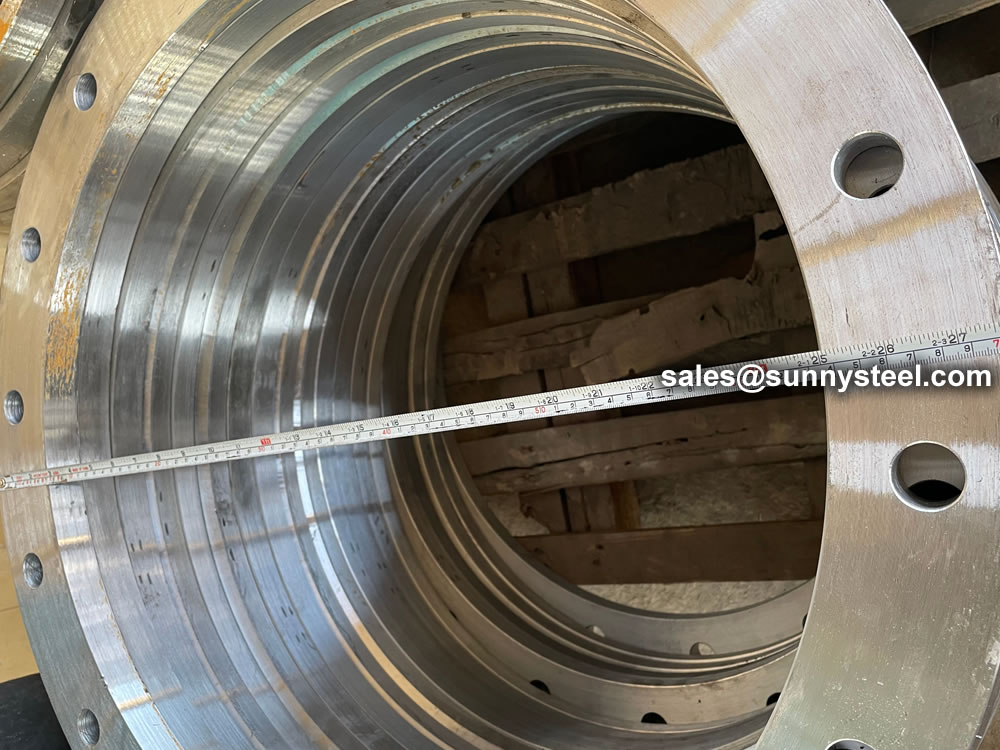
Weldneck orifice flanges are butt-welded into the pipeline. The inside diameter (bore diameter) of the pipe should be specified when ordering. Weldneck orifice flanges are available in ANSI classes 300, 600, 900, 1500 and 2500. They are not available in ANSI 150 sizes because the thickness of ANSI 150 flanges are not enough to allow for drilling pressure taps.
Orifice flanges are used instead of the standard pipe flanges when orifice plate or flow nozzle is used. The basic purpose for this is to measuring the flow rate of either gases or liquids in the respective pipeline. These flanges are used in various industrial applications and are available in various sizes and materials.
Orifice Flange manufacturer Sunny Steel supplies Orifice Flanges, Plate Flanges, Orifice Plates Fittings in alloy steel, forged steel, ductile iron, Stainless Steel etc.
ASME B1.20.1 covers dimensions and gaging of NPT pipe threads for general purpose applications.
Orifice Flanges cover all standard sizes and ranges, and all common Flange materials
Orifice unions come complete with gaskets nuts bolts and jack screws
These flanges are used in the following industries:
Pipe flanges are manufactured in all the different materials like stainless steel, cast iron, aluminium, brass, bronze, plastic etc. but the most used material is forged carbon steel and have machined surfaces.
Flanges are welded to pipe and equipment nozzle. Accordingly, it is manufactured from the following materials;
The list of materials used in manufacturing is covered in ASME B16.5 & B16.47.
Commonly used Forged material grads are
| Material | Fittings | Flanges | Valves | Bolts & Nuts |
|---|---|---|---|---|
| Carbon Steel | A234 Gr WPA | A105 | A216 Gr WCB | A193 Gr B7 A194 Gr 2H |
| A234 Gr WPB | A105 | A216 Gr WCB | ||
| A234 Gr WPC | A105 | A216 Gr WCB | ||
| Carbon Steel Alloy High-Temp |
A234 Gr WP1 | A182 Gr F1 | A217 Gr WC1 | A193 Gr B7 A194 Gr 2H |
| A234 Gr WP11 | A182 Gr F11 | A217 Gr WC6 | ||
| A234 Gr WP12 | A182 Gr F12 | A217 Gr WC6 | ||
| A234 Gr WP22 | A182 Gr F22 | A217 Gr WC9 | ||
| A234 Gr WP5 | A182 Gr F5 | A217 Gr C5 | ||
| A234 Gr WP9 | A182 Gr F9 | A217 Gr C12 | ||
| Carbon Steel Alloy Low-Temp |
A420 Gr WPL6 | A350 Gr LF2 | A352 Gr LCB | A320 Gr L7 A194 Gr 7 |
| A420 Gr WPL3 | A350 Gr LF3 | A352 Gr LC3 | ||
| Austenitic Stainless Steel | A403 Gr WP304 | A182 Gr F304 | A182 Gr F304 | A193 Gr B8 A194 Gr 8 |
| A403 Gr WP316 | A182 Gr F316 | A182 Gr F316 | ||
| A403 Gr WP321 | A182 Gr F321 | A182 Gr F321 | ||
| A403 Gr WP347 | A182 Gr F347 | A182 Gr F347 |
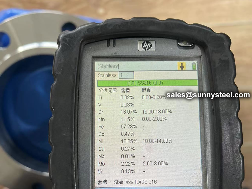
ASTM standards define the specific manufacturing process of the material and determine the exact chemical composition of pipes, fittings and flanges, through percentages of the permitted quantities of carbon, magnesium, nickel, etc., and are indicated by "Grade".
The usual materials of flanges include stainless steel, carbon steel, aluminum and plastic. The choice of the material largely depends on the purpose of the flange. For example, stainless steel is more durable and is necessary for heavy use. On the other hand, plastic is more feasible for use in the home because of its reasonable price and easy installation. The materials used for flanges are under the designation of the American Society of Mechanical Engineers.
The most common materials for pipe flanges (forged grades) are: ASTM A105 (carbon steel high temperature to match A53/A106/API 5L pipes), A350 Grades LF1/2/3 (carbon steel low temperature to match A333 pipes), A694 Grades F42 to F80 (high yield carbon steel to match API 5L pipe grades), ASTM A182 Grades F5 to F91 (alloy steel flanges to match A335 pipes), A182 Grade F304/316 (stainless steel flanges to match A312 SS pipes), A182 Gr. F44/F51/F53/F55 (duplex and super duplex to match A790/A928 pipes) and various nickel alloy grades (Inconel, Incoloy, Hastelloy, Monel).
The material qualities for these flanges are defined in the ASTM standards.
For example, a carbon steel pipe can be identified with Grade A or B, a stainless-steel pipe with Grade TP304 or Grade TP321, a carbon steel fitting with Grade WPB etc.

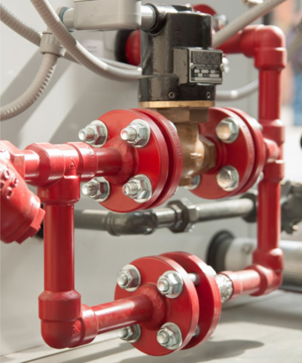
A flange is a method of connecting pipes, valves, pumps, and other equipment to form a piping system. It also provides easy access for cleaning, inspection, or modification.
When a piping joint requires to be dismantled, flanges are being used. These are primarily used on equipment, valves, and specialty items. Breakout flanges are provided at predetermined intervals in certain pipelines where maintenance is a regular occurrence. The flanges, gaskets, and bolting make up a flanged joint, which is made up of three separate but interconnected components. To achieve a leak-proof joint, special controls are required in the selection and application of all of these elements.
Here are the details of Flanges about their advantages and their applications.
Pipes, valves, pumps, and other parts are connected with flanges to form a piping system. Generally, flanges are welded or screwed together. The use of flanges makes pipe system maintenance and repair a breeze. Instead of taking the entire pipe for inspection, a small section of the pipe can be carefully investigated to use a flange to locate the fault.
The following are the five most important benefits of The following are the five most important benefits of flanges:
A flange is a method of connecting pipes, valves, pumps, and other equipment to form a piping system. It also provides easy access for cleaning, inspection, or modification. Flanges are usually welded or screwed.
In many applications, engineers need to find a way to close off a chamber or cylinder in a very secure fashion, usually because the substance inside must differ from the substance outside in composition or pressure.
They do this by fastening two pieces of metal or other material together with a circle of bolts on a lip. This “lip” is a flange.
You can connect two sections of metal piping by soldering or welding them together, but pipes connected in this way are very susceptible to bursting at high pressures. A way of connecting two sections of pipe more securely is by having flanged ends that you can connect with bolts. This way, even if gases or liquids build up to high pressures inside the pipe, it will often hold with no problem.
In order to connect two sections of a large, enclosed area, it is often best to used flanges and bolts. An example of this is the connection between the engine and the transmission in an automobile. In this case, both the engine and the transmission contain a number of moving parts that can easily get damaged if they get dust or other small objects inside of them. By connecting the outer casings of the engine and transmission in this way, engineers protect the inner workings of both.
Flanges have a specific purpose in cameras and other electronic devices. Though flanges in such items do not usually have to sustain high pressures, they do have to hold tight so they can keep out harmful particles. These flanges are usually found connecting two different materials, such as the glass of a lens and the rest of the body of the camera.

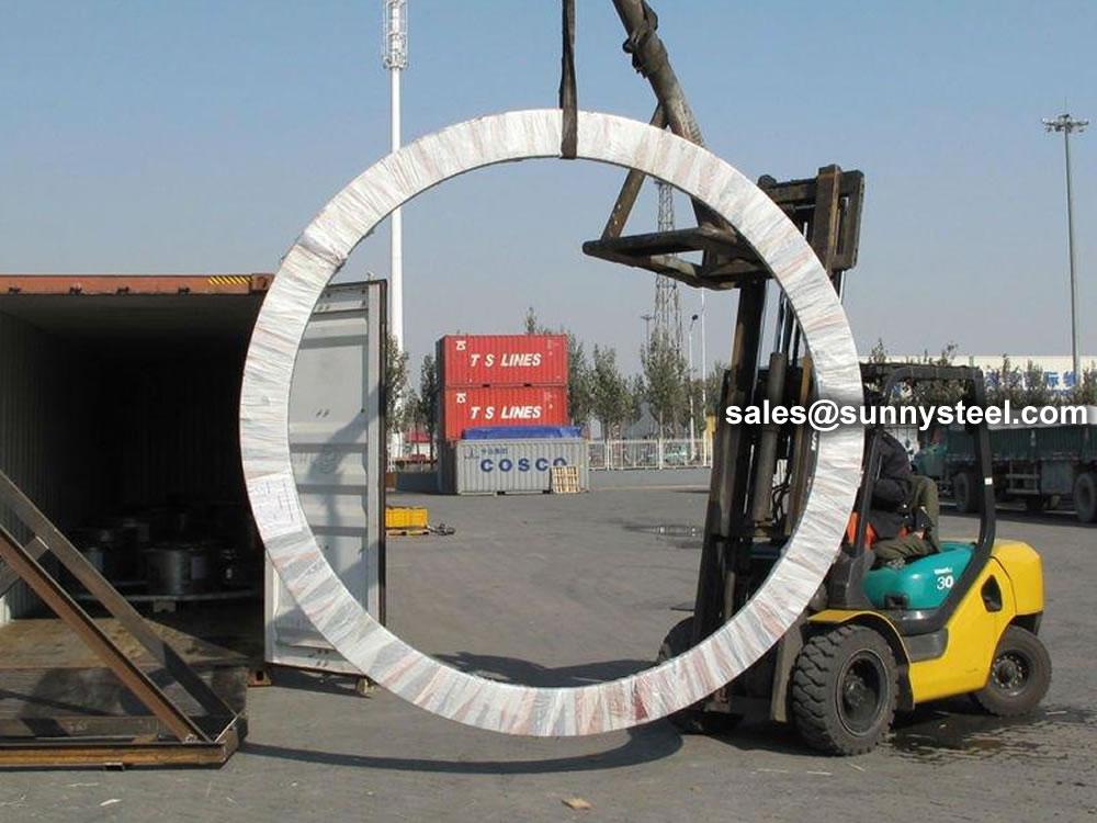
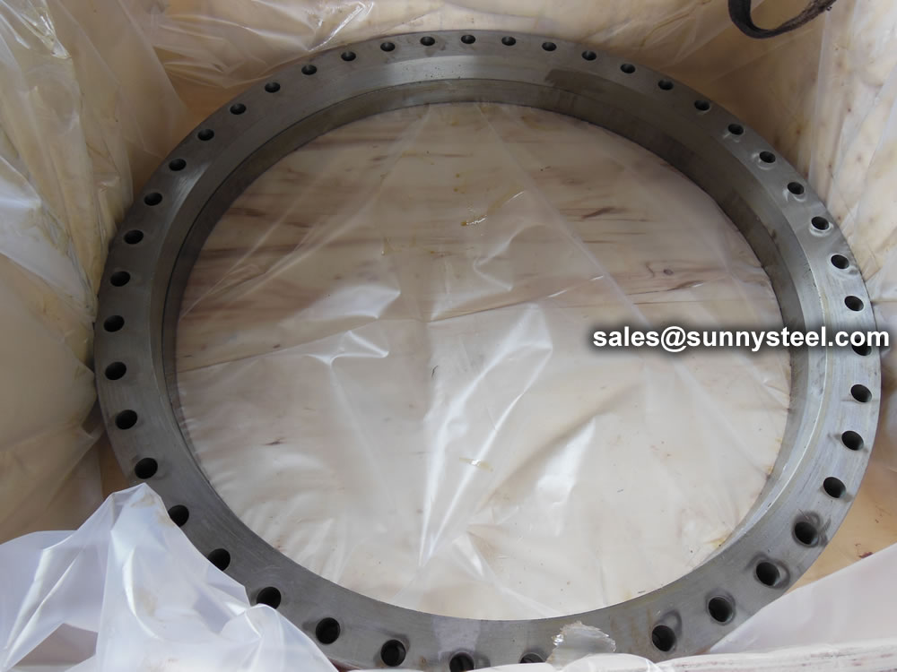
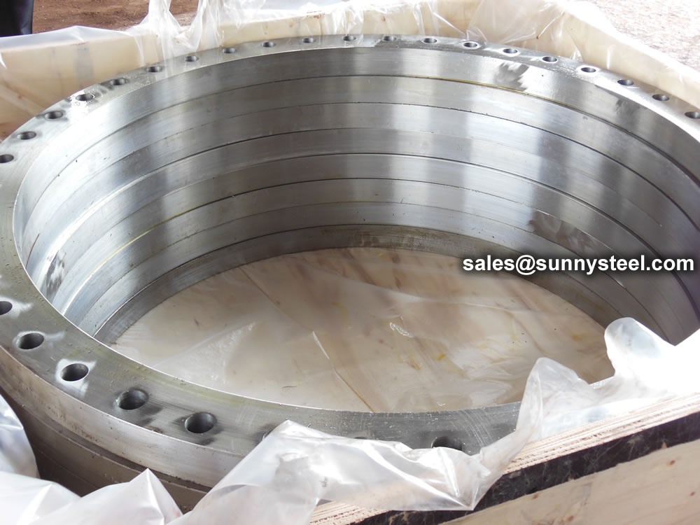
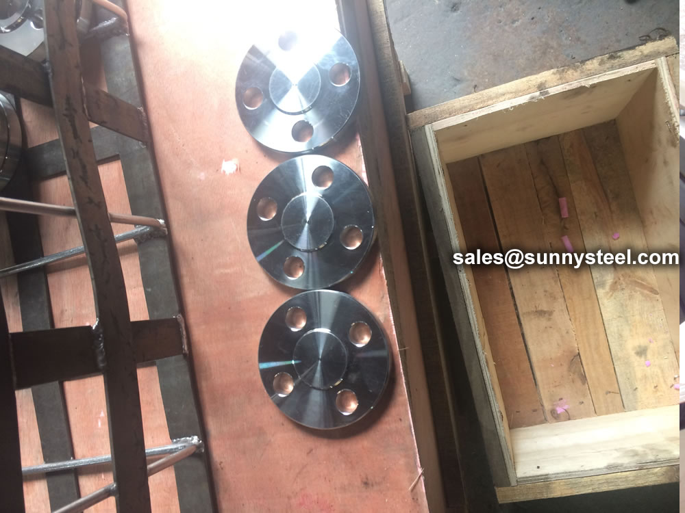
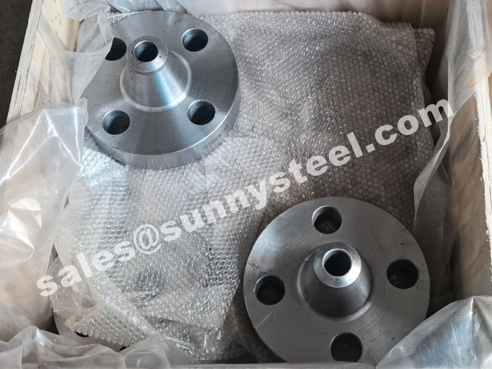
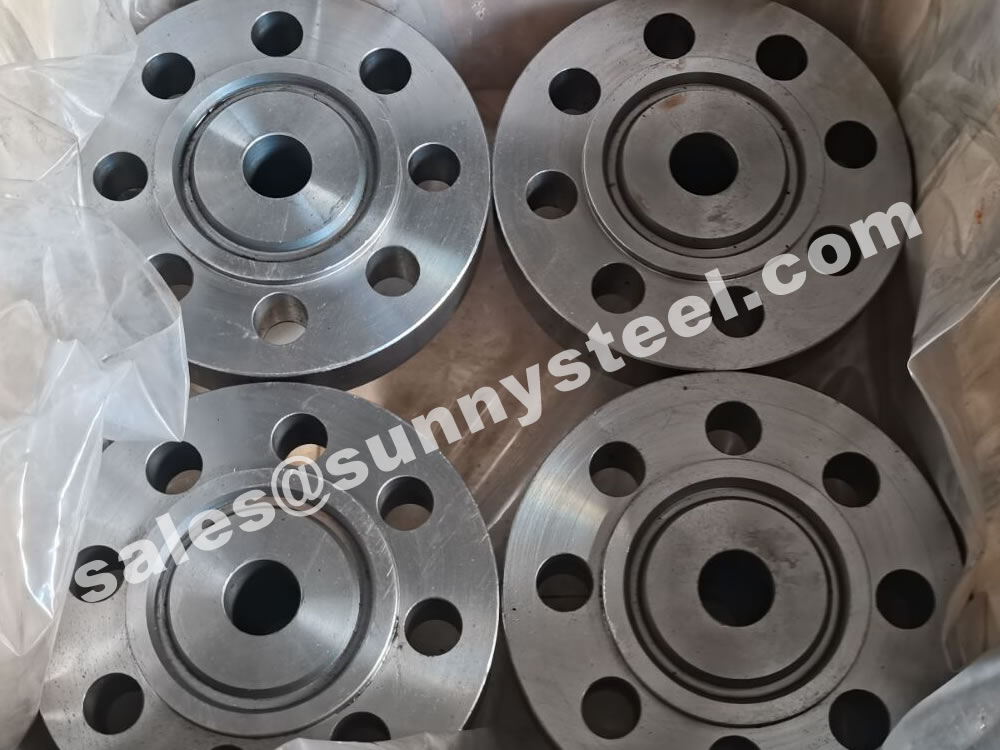
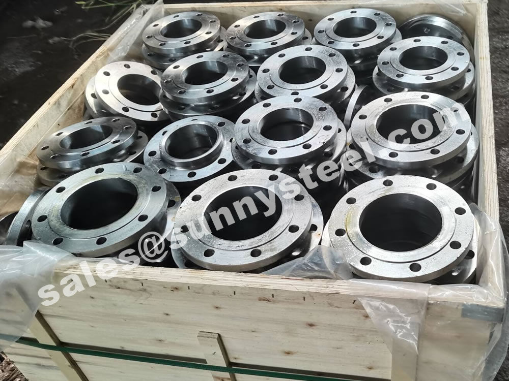
Steel flanges must be packed with seaworthy packing method then delivery to customers, usually the packing way include wooden box, wooden pallet, iron & steel cage, iron & steel pallet etc.
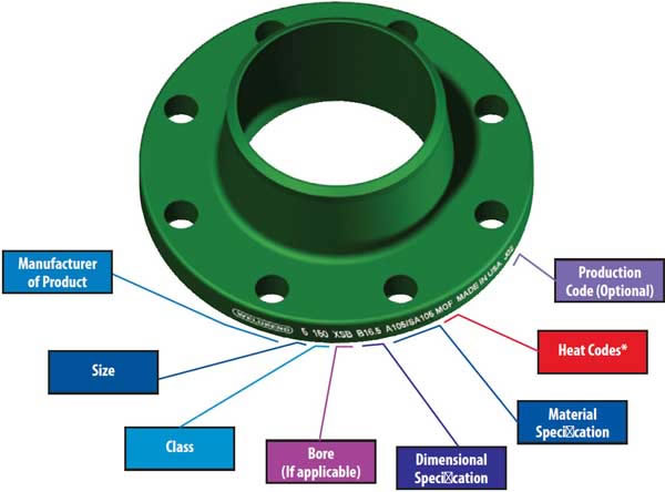
Flange markings are governed by ANSI ASME codes. Flange marking includes;

ASME B16.5 and B16.47 standards cover permissible tolerances for inspection.
Because of the normal wooden boxes or wooden pallets have to do fumigation treatment, we usually use plywood pallet or plywood case or box to pack steel flanges without fumigation treatment.

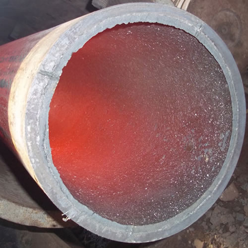
Ceramic lined pipe is made through self-propagating high-temperature synthesis (SHS) technique.
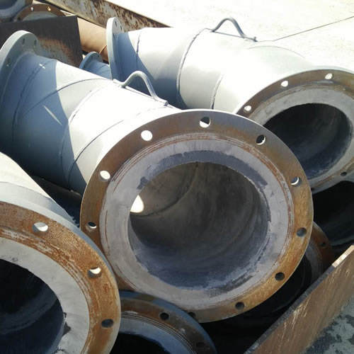
Cast basalt lined steel pipe is composed by lined with cast basalt pipe, outside steel pipe and cement mortar filling between the two layers.
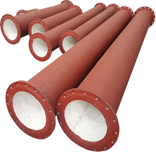
Ceramic tile lined pipes have very uniform coating of specially formulated ceramic material that is affixed to the inner of the pipe.
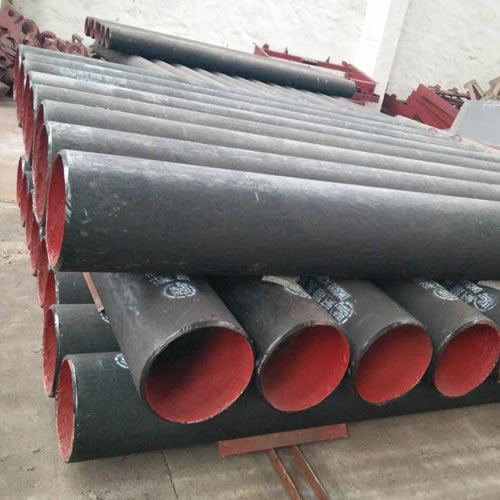
The material of the rare earth alloy wear-resistant pipe is ZG40CrMnMoNiSiRe, which is also the grade of rare earth alloy steel.
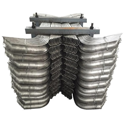
Tubes Erosion Shields are used to protect boiler tubing from the highly erosive effects of high temperatures and pressures thereby greatly extending tube life.
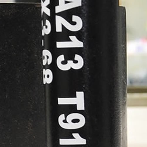
The ASTM A213 T91 seamless tubes are primarily used for boiler, superheater, and heat-exchanger.

When you partner with Sunny Steel, you can stop worrying about meeting deadlines thanks to our responsive and timely service. You'll also say goodbye to unnecessary shopping around. Instead, you'll get white glove service from an expert who understands your needs and can get you the materials you need quickly.