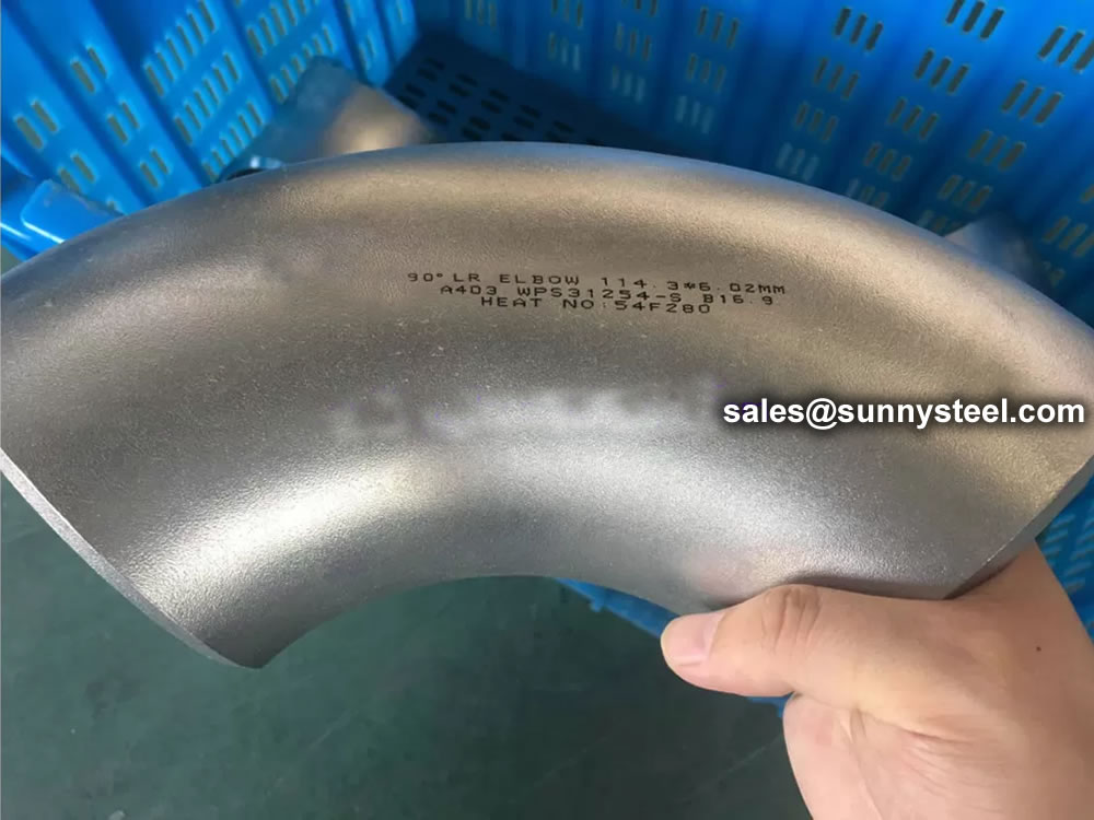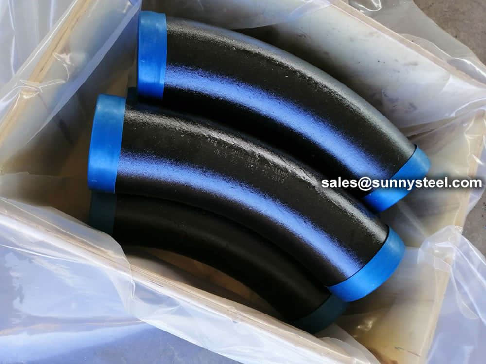
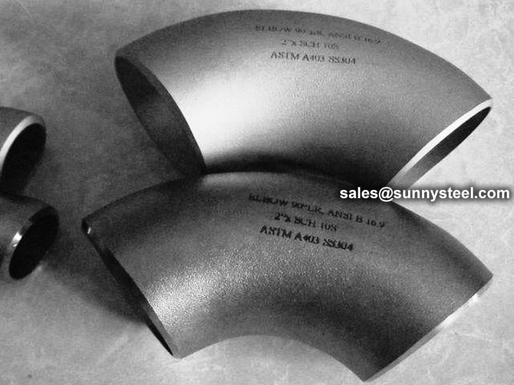
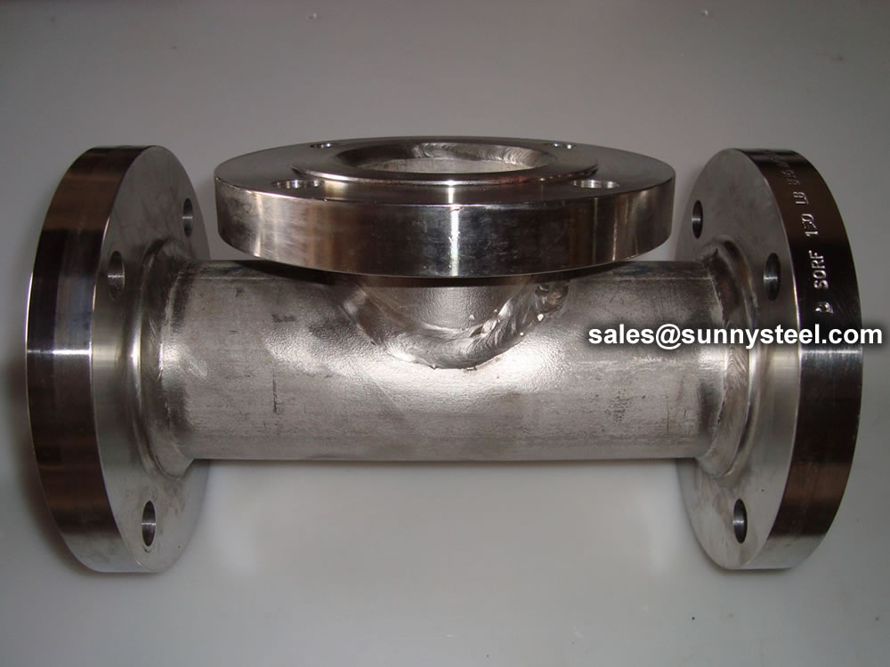
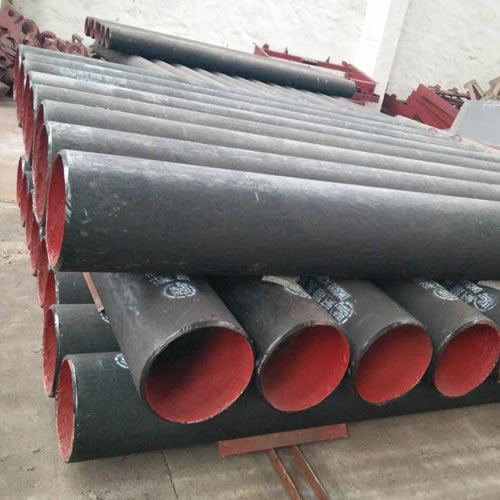
ASTM A403 WP304L Stainless Steel Pipe Elbow
ASTM A403 WP304L Stainless Steel Pipe Elbow - industrial steel product
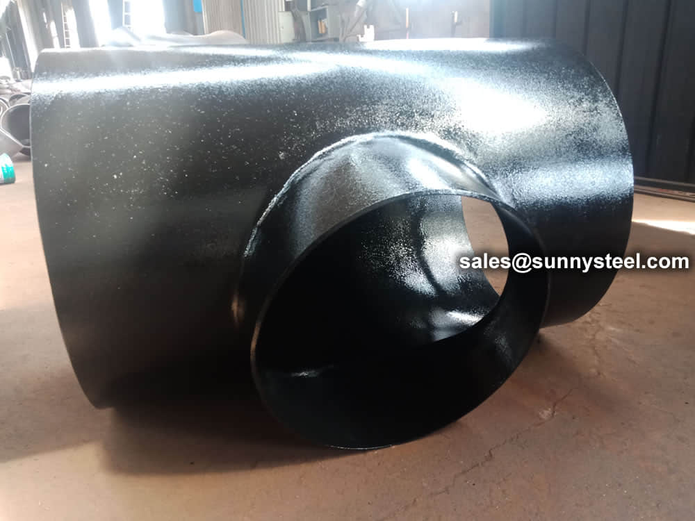
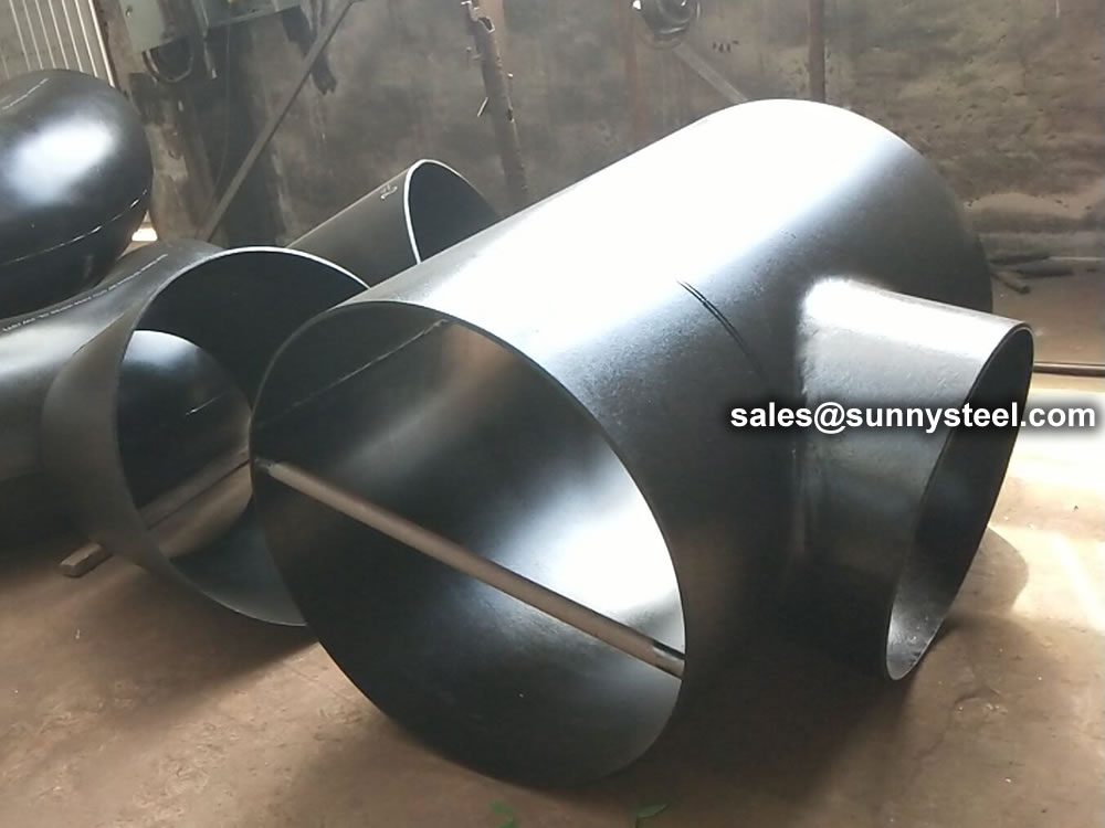
A barred tee, also known as a branch connection tee, is a specialized fitting widely used in piping systems to direct fluid flow from the main pipeline to a branch line.
Barred tee is a pipe fitting that is used in a pig launcher or receiver system in a piping system to ensure the pig could pass the branch safely.
Download PDF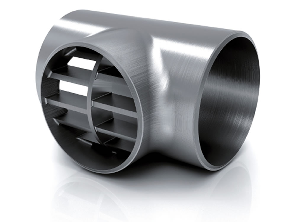
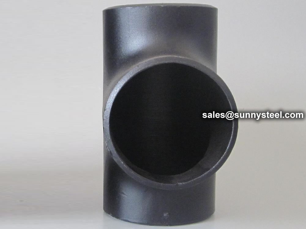
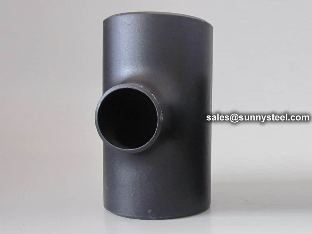
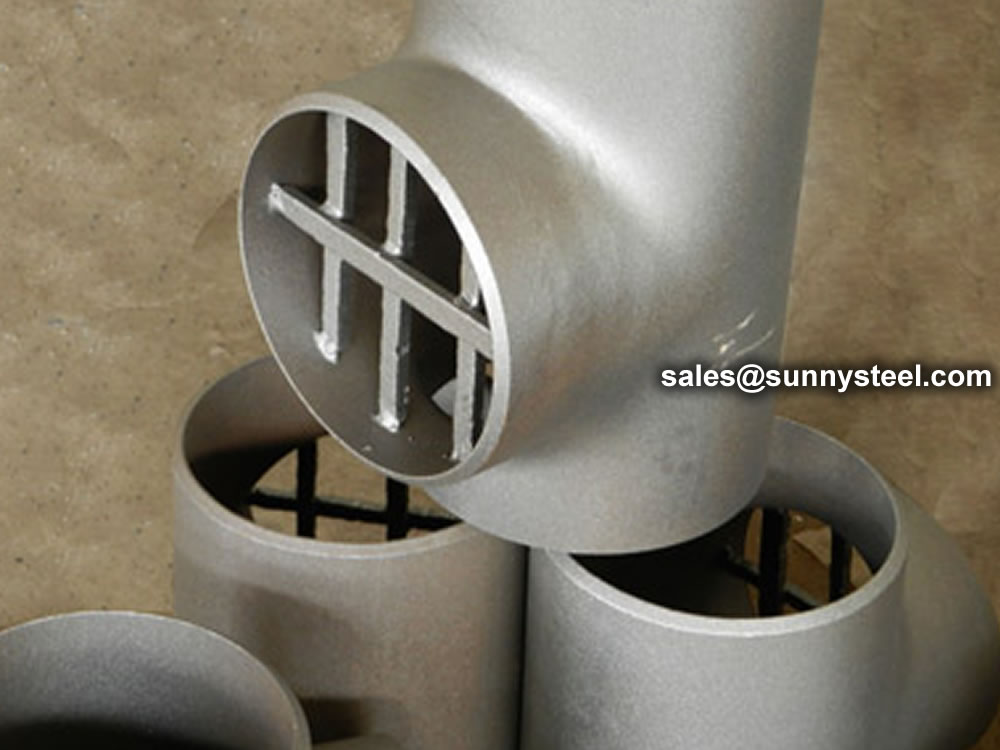
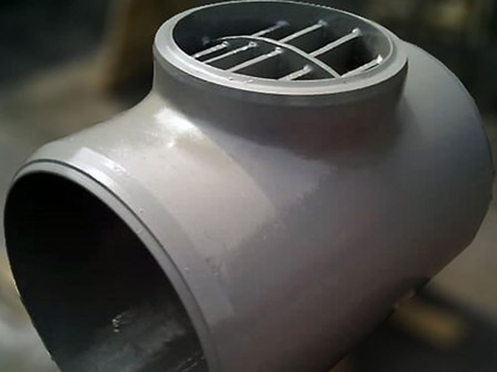
Barred tees, also known as branch outlet fittings or lateral tees, are a type of pipe fitting used in piping systems to create a branch connection at a 90-degree angle. What distinguishes barred tees from regular tees is the presence of a solid or reinforcing bar across the run of the tee. This bar helps provide structural support to the branch connection, especially in high-pressure and high-temperature applications.
The bar in a barred tee prevents direct fluid flow through the branch, which can be useful in certain scenarios. Barred tees are often used in applications where one pipe needs to be temporarily isolated or shut off, allowing for maintenance, inspection, or repairs on the connected branch without shutting down the entire system.
Barred tees are commonly manufactured from the same materials as regular tees, such as carbon steel, stainless steel, and other alloys. They are utilized in various industries, including oil and gas, petrochemicals, power generation, and more, where safety, durability, and efficient branch connections are essential.
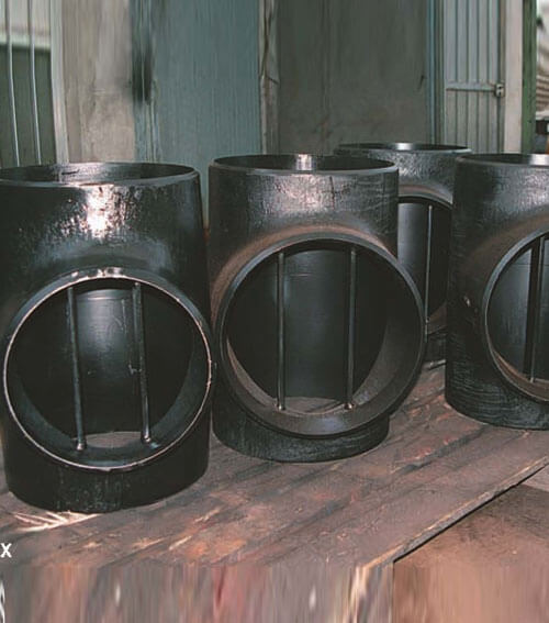
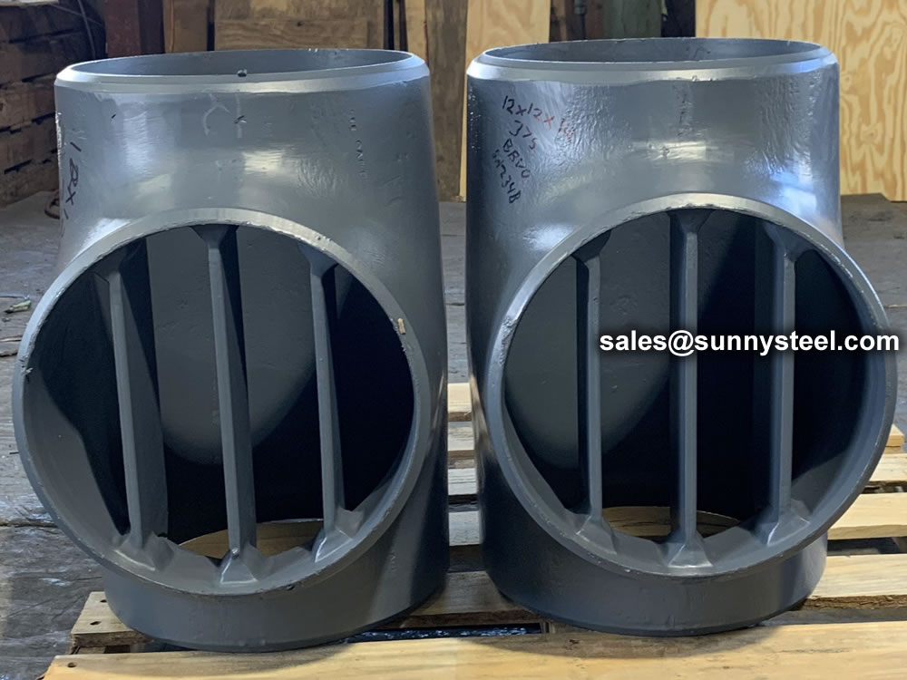
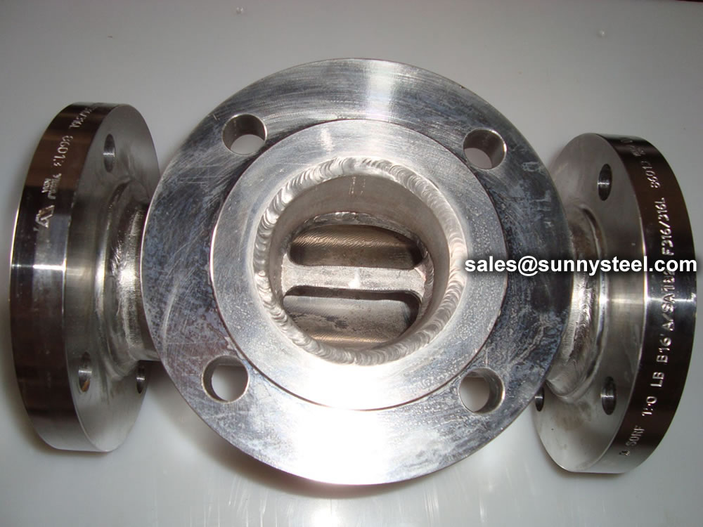
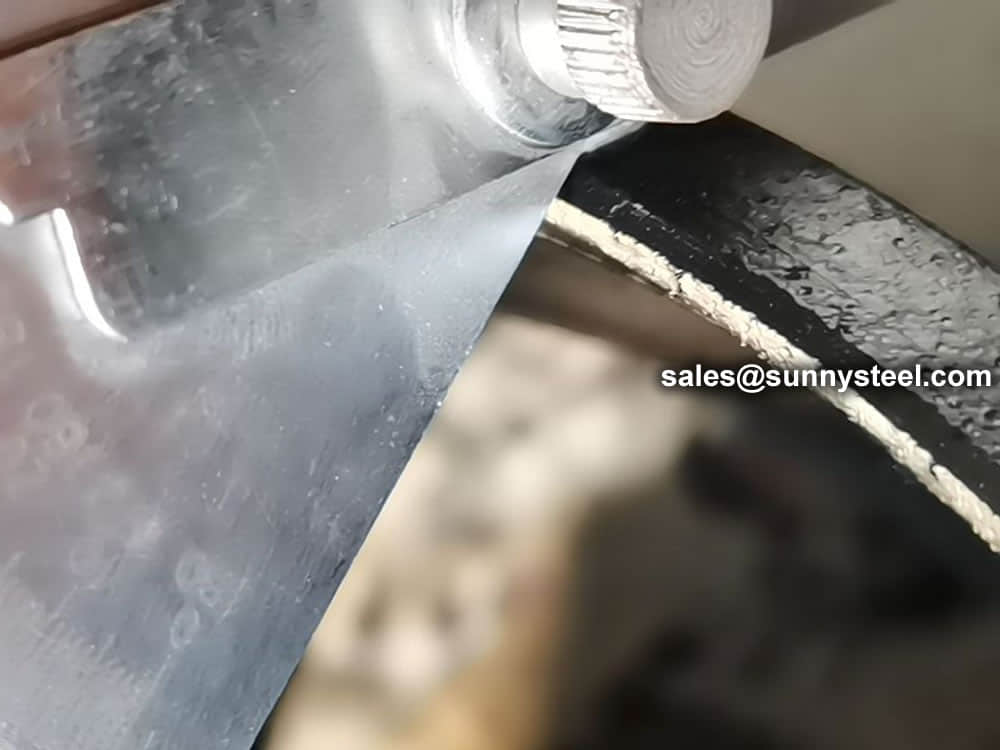
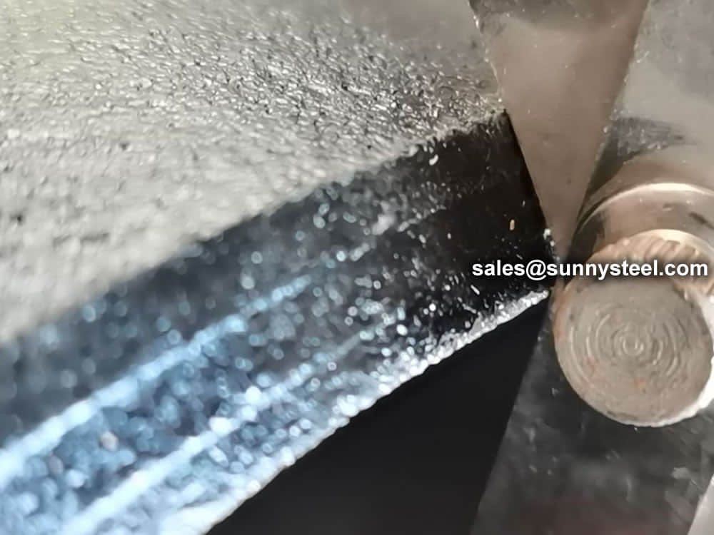
The barred tee will be used when there is a requirement for pigging. Thus, many of its applications can be found in the pipeline or in the subsea field. The bar plates that are welded internally at the branch are to avoid the pig from changing direction or getting stuck at the branch outlet.
Barred tees are pipe fittings with two outlets, one at 90 В° to the connection to the main line that has tiny holes. Barred tees can either be extruded or fabricated and are used to connect two pieces of pipe or fittings. Barred tee is used in pipelines that are pigged.
Here are a few renowned manufacturers of barred tees in the industry:
MSS SP-75 Barred Tee - This manufacturer specializes in providing high-quality barred tees that adhere to the MSS SP-75 standard. They offer a wide range of sizes, materials, and specifications to meet different project requirements.
ANSI B16.9 Barred Tee Manufacturer - This manufacturer produces barred tees according to ANSI B16.9 standards. They offer custom solutions for various industries, ensuring reliable and safe branch connections.
ASME Barred Tee Supplier - With a focus on ASME compliance, this manufacturer offers a diverse selection of barred tees suitable for critical applications. They provide solutions for both standard and customized specifications.
Special Alloy Barred Tee Manufacturer - If you require barred tees made from special alloys like stainless steel, duplex, or super duplex materials, this manufacturer specializes in producing these customized fittings to cater to specific corrosion resistance and strength needs.
Oil & Gas Industry Barred Tees - This manufacturer has a strong presence in the oil and gas sector, producing barred tees designed to withstand the demanding conditions of offshore and onshore installations.
Power Generation Barred Tee Supplier - For power plants and energy projects, this manufacturer offers barred tees engineered to handle high-temperature and high-pressure environments, ensuring reliable branch connections.
Custom Fabricated Barred Tees - If you require unique dimensions or configurations, this manufacturer specializes in custom fabricating barred tees to your exact specifications, ensuring a perfect fit for your piping systems.
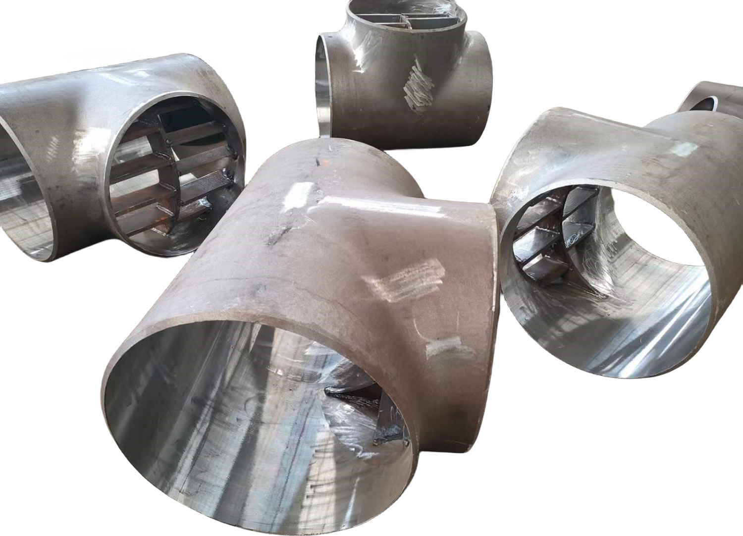
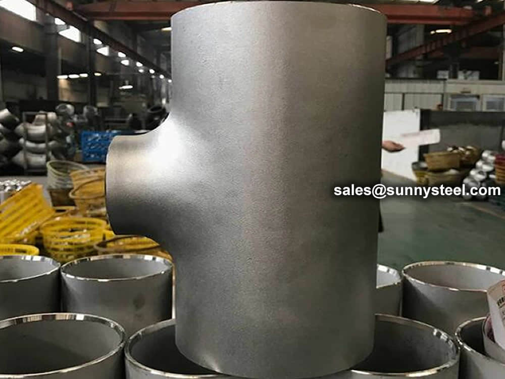
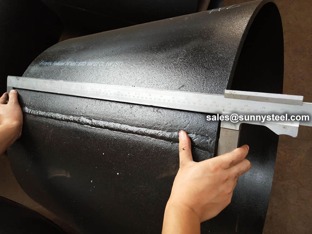
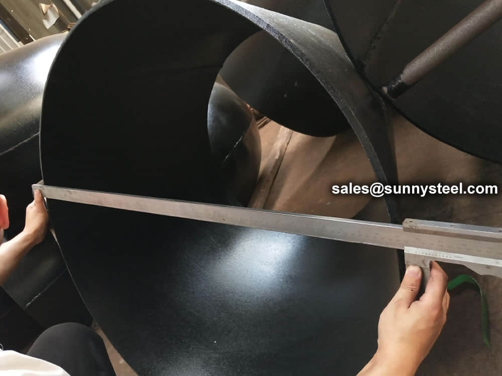
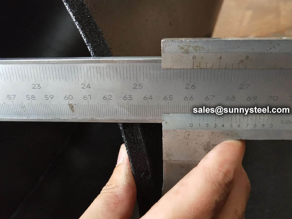
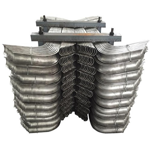
The Barred Tee being processed
Flow Control: Barred tees offer a reliable means of controlling and directing fluid flow, eliminating the need for additional valves or equipment.
Pressure Drop Minimization: The unique design of barred tees minimizes pressure drop and turbulence, ensuring efficient flow while optimizing energy consumption.
Space Efficiency: Barred tees provide a compact solution for flow diversion, making them suitable for installations where space is limited.
When incorporating barred tees into a piping system, several factors must be considered:
Flow Characteristics: Analyze the fluid properties, flow rates, and operational requirements to determine the appropriate bar configuration and branch angle.
Material Compatibility: Select the material that is compatible with the fluid being transported and capable of withstanding the operating conditions.
Pressure and Temperature: Ensure that the barred tee can handle the pressure and temperature conditions of the system without compromising performance.
The barred tee, with its distinctive design and versatile applications, emerges as a critical component in optimizing fluid flow in piping systems across industries. Its ability to provide controlled flow management, minimize pressure drop, and enhance fluid dynamics makes it an invaluable asset in achieving seamless and efficient operation. By understanding its design principles, advantages, and considerations, engineers and professionals can harness the power of barred tees to enhance fluid flow management and system performance.
The Piggable Tee serves as both supply and discharge points within the pigged transfer line.Our Piggable Tees are designed with a compact tee branch length and an integrated tee branch pig bar. This unique design ensures the seamless passage of the pig through the tee, preventing any obstructions in the tee branch and minimizing the retention of residual product in the dead leg of the tee branch.
The concise length of the tee branch effectively reduces the dead leg in the branch, preventing residual product from flowing back into the line once the pig passes through. This means that any remaining product in the transfer line is minimal, and it gets pushed from the main line to the demister as the pig is directed back to the pig launcher.
Although the tee branch pig bars are not permanently affixed by welding, they ensure the pig's smooth and reliable passage under the tee branch without any hang-ups. Except for sanitary piggable tees, which require specific sanitary design considerations, the tee branch pig bar is an integral part of the main line piping. This guarantees that the pig bar maintains the same curved shape as the pipe, ensuring a seamless transition through the tee.
Piping Tees are used either for dividing main flow in two streams or for combining flow from two streams. Tees are normal or perpendicular to the pipe axis and normally produced by forging and are designed based on ASME B 16.9 or ASME B 16.11.
Barred tee is the special type of tee and is designed like adding bar plates inside the branch outlet on a normal tee. In pig launcher or receiver system, barred tee is used to ensure the pig could pass the branch safely.There is no international standard dimension for the barred tee. It is custom-made using the ASME B16.9/ MSS-SP 75 tee as a base with or without the help of Shell DEP 31.40.10.13-Gen or ISO 15590-2 standard.
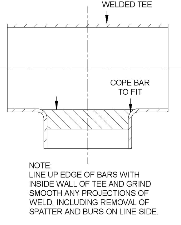
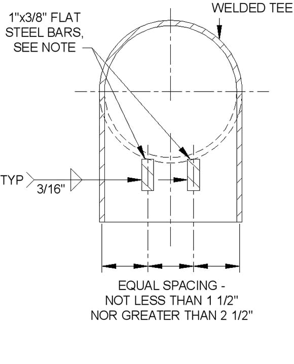
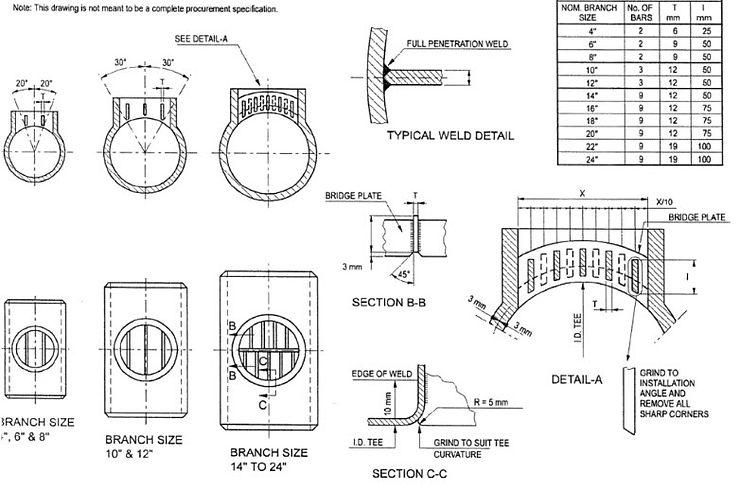
The bar plates in sufficient quantity, thickness, and adequately spaced are welded internally at the branch to ensure the smoothness for the pig to run through the main pipe, and at the same time not affect the flow direction or getting stuck at the branch outlet. The bars are to be small enough not to restrict the flow but large enough to sustain the pressure of the flow. Sharp edges and burs are removed and the bars are to be grind to the branch curvature inorder to protect the pig sensors from damage. Bar plates are made with same material for weldability. Weld Repairs on Parent metal are prohibited. Standard practice is to avoid welding guide bars directly on the high-stress concentrated areas of the extrusion neck. Bar ends must be machined to fit the branch.
In piping engineering, a Tee or Tee connection is a very significant pipe fitting that is regularly used to join or divide a flow. There are 2 types of tees available: equal tee and reducing tee. However, in pigged pipelines, a unique type of tee connection called the Barred Tee or Pigged Tee is often utilized. In this article, we will look at a few aspects of the barred tee and tee connections.
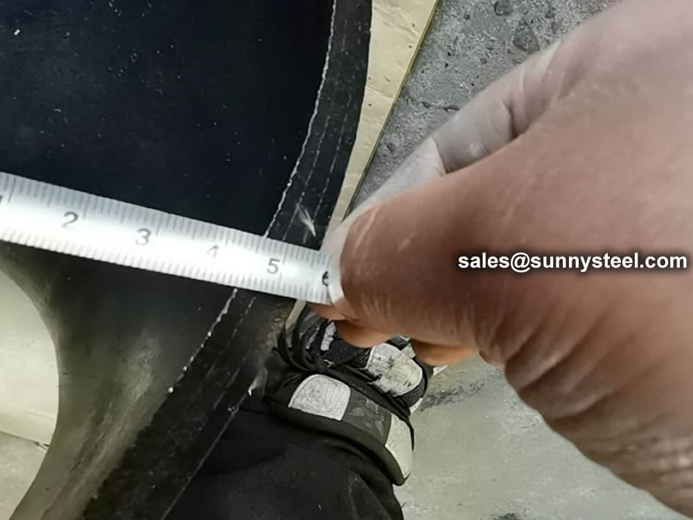
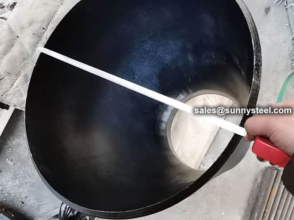
This table provides the dimensions for Barred Tees, including nominal pipe sizes, outside diameters at bevel, and center-to-end measurements for both run and outlet.
| Nominal Pipe Size (NPS) | Outside Diameter at Bevel (mm) | Center-to-End Run (C) (mm) | Center-to-End Outlet (M) (mm) |
|---|---|---|---|
| 1/2" x 1/4" | 21.3 x 13.7 | 25 | 25 |
| 3/4" x 3/8" | 26.7 x 17.3 | 29 | 29 |
| 1" x 1/2" | 33.4 x 21.3 | 38 | 38 |
| 1 1/4" x 1" | 42.2 x 33.4 | 48 | 48 |
| 1 1/2" x 1 1/4" | 48.3 x 42.2 | 57 | 57 |
| 2" x 1 1/2" | 60.3 x 48.3 | 64 | 60 |
| 2 1/2" x 2" | 73.0 x 60.3 | 76 | 70 |
| 3" x 2 1/2" | 88.9 x 73.0 | 86 | 83 |
| 3 1/2" x 3" | 101.6 x 88.9 | 95 | 92 |
| 4" x 3 1/2" | 114.3 x 101.6 | 105 | 102 |
| 5" x 4" | 141.3 x 114.3 | 124 | 117 |
| 6" x 5" | 168.3 x 141.3 | 143 | 137 |
| 8" x 6" | 219.1 x 168.3 | 178 | 168 |
| 10" x 8" | 273.0 x 219.1 | 216 | 203 |
| 12" x 10" | 323.8 x 273.0 | 254 | 241 |
| 14" x 12" | 355.6 x 323.8 | 279 | 270 |
| 16" x 14" | 406.4 x 355.6 | 305 | 305 |
| 18" x 16" | 457.0 x 406.4 | 343 | 330 |
| 20" x 18" | 508.0 x 457.0 | 381 | 368 |
| 22" x 20" | 559.0 x 508.0 | 419 | 406 |
| 24" x 22" | 610.0 x 559.0 | 432 | 432 |
Note: The above dimensions are based on standard specifications and may vary depending on specific manufacturing requirements.
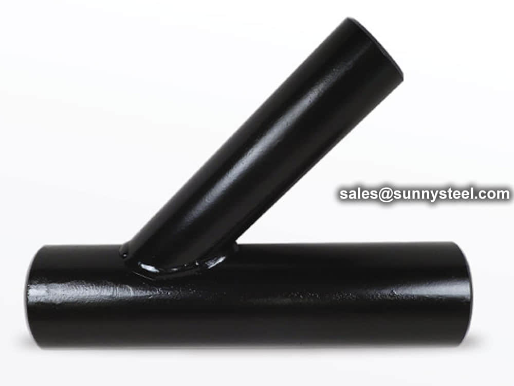
TeeВ ~A tee is a type of fitting that enables fluid to flow through its main pipe and branch out. The branch might be constructed to be the equivalent size of the main pipe (known as an Equal Tee) or smaller in size than the main pipe (known as a Reducing Tee).
What is a barred tee?В ~A barred tee is a particular type of tee that is built from a standard tee (either an equal or a reducing tee) and is afterward installed with bar plates inside the branch outlet (from the inside, it looks like a steel cage) to prevent the pig from flowing from the header pipe into the branch pipes. Barred Tee is much costlier than normal tee.

Tee is a type of fittings that allows fluid to flow on its main pipe and branch out. The branch can be designed equally the same size as the main pipe (known as Equal Tee), or smaller size than the main pipe (known as Reducing Tee).
Barred Tee is a special type of Tee that base from a normal tee (can be either equal tee or reducing tee) that at later stage, will be added with bar plates inside the branch outlet (From inside it looks like a steel cage) to restrict the pig from flowing from the header pipe into the branch pipes.
Barred Tee is a special type of tee that base from a normal tee (can be either equal tee or reducing tee) that at later stage, will be added with bar plates inside the branch outlet (From inside it looks like a steel cage) to restrict the pig from flowing from the header pipe into the branch pipes.
Tee or Tee connection in piping engineering is a very important pipe fitting and is frequently used to combine or divide a flow. Two types of Tee are available, Equal Tee and Reducing Tee. However, in pigged pipelines, one special type of tee connection is widely used which is known as Barred Tee or Pigged Tee.
So from the above discussion, we can summarize the following differences:
| Parameter | Tee | Barred Tee |
|---|---|---|
| Definition | Standard Pipe Fitting | A special type of piping component |
| Manufacturing | Generally by Extrusion or forging | Mostly Fabricated |
| Use | Used in both piping and pipeline engineering | used in pipeline engineering near the pig launcher/receiver |
| Design Code / Standard | ASME B 16.9/MSS SP 75 | Shell DEP 31.40.10.13-Gen or ISO 15590-2 |
| Production Quantity | Large scale in bulk | Select small quantities (custom made) |
| Cost | Cheaper | Costlier than normal Tee |

Q: What is a barred tee used for?
A: A barred tee is a specialized fitting used in piping systems to direct fluid flow from the main pipeline to a branch line while controlling and diverting the flow.
Q: What are the advantages of using barred tees?
A: Barred tees offer precise flow control, minimized pressure drop, and efficient space utilization, making them valuable in industries requiring controlled fluid management.
Q: How can I select the right barred tee for my application?
A: Consider factors such as flow characteristics, material compatibility, pressure, and temperature conditions to choose the appropriate barred tee for your piping system.
Q:What are the requirements for barred tee?
A:The bar plates must be of good quantity, thickness, and spacing for the pig to maintain a smooth flow through the pipe with no interference from the branch.
Q:What is the design code for barred tee?
A:Barred tee actually is the BW tee welded with bars. Design code ASME B16. 9 or MSS-SP 75 and Shell DEP 31.40. 10.13-Gen or ISO 15590-2.
Q:What is the purpose of barred tee in pipeline?
A:Barred Tees are used in a pipeline system at any branch in the pipeline to ensure safe passage of the Pig.


Pipe fitting dimensions are in either metric or Standard English.
Because pipe fitting covers Pipe Fitting Dimensions several aspects, only the most common pipe fitting sizes can be given here. The most applied version is the 90В° long radius and the 45В° elbow, while the 90В° short radius elbow is applied if there is too little space. The function of a 180В° elbow is to change direction of flow through 180В°. Both, the LR and the SR types have a center to center dimension double the matching 90В° elbows. These fittings will generally be used in furnesses or other heating or cooling units.
Some of the standards that apply to buttwelded fittings are listed below. Many organizations such as ASME, ASTM, ISO, MSS, etc. have very well developed standards and specifications for buttwelded fittings. It is always up to the designer to ensure that they are following the applicable standard and company specification, if available, during the design process.
Some widely used pipe fitting standards are as follows:
This is one of the reputed organizations in the world developing codes and standards.
The schedule number for pipe fitting starts from ASME/ANSI B16. The various classifications of ASME/ANSI B16 standards for different pipe fittings are as follows:
This is one of the largest voluntary standards development organizations in the world. It was originally known as the American Society for Testing and Materials (ASTM).
AWWA About вҖ“ Established in 1881, the American Water Works Association is the largest nonprofit, scientific and educational association dedicated to managing and treating water, the worldвҖҷs most important resource.
ANSI is a private, non-profit organization. Its main function is to administer and coordinate the U.S. voluntary standardization and conformity assessment system. It provides a forum for development of American national standards. ANSI assigns "schedule numbers". These numbers classify wall thicknesses for different pressure uses.
The Manufacturers Standardization Society (MSS) of the Valve and Fittings Industry is a non-profit technical association organized for development and improvement of industry, national and international codes and standards for: Valves, Valve Actuators, Valve Modification, Pipe Fittings, Pipe Hangers, Pipe Supports, Flanges and Associated Seals
Piping codes imply the requirements of design, fabrication, use of materials, tests and inspection of various pipe and piping system. It has a limited jurisdiction defined by the code. On the other hand, piping standards imply application design and construction rules and requirements for pipe fittings like adapters, flanges, sleeves, elbows, union, tees, valves etc. Like a code, it also has a limited scope defined by the standard.
"Standards" on pipe fittings are based on certain factors like as follows:
BSP is the U.K. standard for pipe fittings. This refers to a family of standard screw thread types for interconnecting and sealing pipe ends by mating an external (male) with an internal (female) thread. This has been adopted internationally. It is also known as British Standard Pipe Taper threads (BSPT )or British Standard Pipe Parallel (Straight) threads (BSPP ). While the BSPT achieves pressure tight joints by the threads alone, the BSPP requires a sealing ring.
This is the Japanese industrial standards or the standards used for industrial activities in Japan for pipe, tube and fittings and published through Japanese Standards Associations.
National Pipe Thread is a U.S. standard straight (NPS) threads or for tapered (NPT) threads. This is the most popular US standard for pipe fittings. NPT fittings are based on the internal diameter (ID) of the pipe fitting.
We are manufacturer of Flange bolts & Nuts and supply high quality
The AN standard was originally designed for the U.S. Military. Whenever, a pipe fitting is AN fittings, it means that the fittings are measured on the outside diameter of the fittings, that is, in 1/16 inch increments.
For example, an AN 4 fitting means a fitting with an external diameter of approximately 4/16вҖі or Вј”. It is to be noted that approximation is important because AN external diameter is not a direct fit with an equivalent NPT thread.
Dash size is the standard used to refer to the inside diameter of a hose. This indicates the size by a two digit number which represents the relative ID in sixteenths of an inch. This is also used interchangeably with AN fittings. For example, a Dash "8" fitting means an AN 8 fitting.
ISO is the industrial pipe, tube and fittings standards and specifications from the International Organization for Standardization. ISO standards are numbered. They have format as follows:
"ISO[/IEC] [IS] nnnnn[:yyyy] Title" where
| Standard | Specification |
|---|---|
| ASTM A234 | Standard Specification for Piping Fittings of Wrought Carbon Steel and Alloy Steel for Moderate and High Temperature Service |
| ASTM A420 | Standard Specification for Piping Fittings of Wrought Carbon Steel and Alloy Steel for Low-Temperature Service |
| ASTM A234 WPB | ASTM A234 WPB refers to a specific grade of carbon steel pipe fittings, which are widely used in pressure piping and pressure vessel fabrication for service at moderate and elevated temperatures. |
| ASME B16.9 | ASME B16.9 Standard covers overall dimensions, tolerances,ratings, testing, and markings for factory-made wrought buttwelding fittings in sizes NPS 1вҒ„2 through NPS 48 (DN 15 through DN 1200). |
| ASME B16.28 | ASME B16.28 Standard covers ratings, overall dimensions, testing, tolerances, and markings for wrought carbon and alloy steel buttwelding short radius elbows and returns. |
| MSS SP-97 | MSS SP-97 Standard Practice covers essential dimensions, finish, tolerances, testing, marking, material, and minimum strength requirements for 90 degree integrally reinforced forged branch outlet fittings of buttwelding, socket welding, and threaded types. |
| ASTM A403 | Standard Specification for Wrought Austenitic Stainless Steel Piping Fittings. |
| DIN | EN | ASME |
|---|---|---|
| St 35.8 I St 35.8 III 15 Mo 3 13 CrMo 4 4 10 CrMo 9 10 St 35 N St 52.0 St 52.4 |
P235GH-TC1 P235GH-TC2 16Mo3 13CrMo4-5 10CrMo9-10 X10CrMoVNb9-1 P215NL P265NL L360NB L360NE P355N P355NL1 P355NH |
WPB WPL6 WPL3 WPHY 52 WP11 WP22 WP5 WP9 WP91 WP92 |
ASTM A234/A234M is a standard specification for piping fittings of wrought carbon steel and alloy steel for moderate and high-temperature service. This specification covers several grades of fittings that are used in various applications in the oil and gas, petrochemical, and power generation industries.
Download PDF| Grade | Type | C | Si | S | P | Mn | Cr | Ni | Mo | Other | Гіb | Гіs | Оҙ5 |
|---|---|---|---|---|---|---|---|---|---|---|---|---|---|
| WPB | 0.3 | 0.1min | 0.058 | 0.05 | 0.29-1.06 | 0.4 | 0.4 | 0.15 | V:0.06;Nb:0.02 | 415-585 | 240 | 22 | 197 |
| WPC | 0.35 | 0.1min | 0.058 | 0.05 | 0.29-1.06 | 0.4 | 0.4 | 0.15 | V:0.06;Nb:0.02 | 485-655 | 275 | 22 | 197 |
| WP1 | 0.28 | 0.1-0.5 | 0.045 | 0.045 | 0.3-0.9 | 0.44-0.65 | 380-550 | 205 | 22 | 197 | |||
| WP12 CL1 | 0.05-0.2 | 0.6 | 0.045 | 0.045 | 0.3-0.8 | 0.8-1.25 | 0.44-0.65 | 415-585 | 220 | 22 | 197 | ||
| WP12 CL2 | 0.05-0.2 | 0.6 | 0.045 | 0.045 | 0.3-0.8 | 0.8-1.25 | 0.44-0.65 | 485-655 | 275 | 22 | 197 | ||
| WP11 CL1 | 0.05-0.15 | 0.5-1 | 0.03 | 0.03 | 0.3-0.6 | 1-1.5 | 0.44-0.65 | 415-585 | 205 | 22 | 197 | ||
| WP11 CL2 | 0.05-0.2 | 0.5-1 | 0.04 | 0.04 | 0.3-0.8 | 1-1.5 | 0.44-0.65 | 485-655 | 275 | 22 | 197 | ||
| WP11 CL3 | 0.05-0.2 | 0.5-1 | 0.04 | 0.04 | 0.3-0.8 | 1-1.5 | 0.44-0.65 | 520-690 | 310 | 22 | 197 | ||
| WP22 CL1 | 0.05-0.15 | 0.5 | 0.04 | 0.04 | 0.3-0.6 | 1.9-2.6 | 0.87-1.13 | 415-585 | 205 | 22 | 197 | ||
| WP22 CL3 | 0.05-0.15 | 0.5 | 0.04 | 0.04 | 0.3-0.6 | 1.9-2.6 | 0.87-1.13 | 520-690 | 310 | 22 | 197 | ||
| WP5 CL1 | 0.15 | 0.5 | 0.03 | 0.04 | 0.3-0.6 | 4-6 | 0.44-0.65 | 415-585 | 205 | 22 | 217 | ||
| WP5 CL3 | 0.15 | 0.5 | 0.03 | 0.04 | 0.3-0.6 | 4-6 | 0.44-0.65 | 520-690 | 310 | 22 | 217 | ||
| WP9 CL1 | 0.15 | 1 | 0.03 | 0.03 | 0.3-0.6 | 8-10 | 0.9-1.1 | 415-585 | 205 | 22 | 217 | ||
| WP9 CL3 | 0.15 | 1 | 0.03 | 0.03 | 0.3-0.6 | 8-10 | 0.9-1.1 | 520-690 | 310 | 22 | 217 | ||
| WPR | 0.2 | 0.05 | 0.045 | 0.4-1.06 | 1.6-2.24 | 435-605 | 315 | 22/28 | 217 | ||||
| WP91 | 0.08-0.12 | 0.2-0.5 | 0.01 | 0.02 | 0.3-0.6 | 8-9.5 | 0.4 | 0.85-1.05 | See sdandard | 585-760 | 415 | 20 | 248 |
| WP911 | 0.09-0.13 | 0.1-0.5 | 0.01 | 0.02 | 0.3-0.6 | 8.5-10.5 | 0.4 | 0.9-1.1 | See sdandard | 620-840 | 440 | 20 | 248 |
For each reduction of 0.01% below the specified C maximum, an increase of 0.06% Mn above the specified maximum will be permitted, up to a maximum of 1.35%.
The sum of Cu, Ni, Cr, and Mo shall not exceed 1.00%.
The sum of Cr and Mo shall not exceed 0.32%.
The maximum carbon equivalent (C.E.) shall be 0.50, based on heat analysis and the formula C.E.=C+Mn/6+(Cr+Mo+V)/5+(Ni+Cu)/15.
| Tensile Requirements | WPB | WPC, WP11CL2 | WP11CL1 | WP11CL3 |
|---|---|---|---|---|
| Tensile Strength, min, ksi[MPa] (0.2% offset or 0.5% extension-under-load) |
60-85 [415-585] |
70-95 [485-655] |
60-85 [415-585] |
гҖҖ75-100 [520-690] |
| Yield Strength, min, ksi[MPa] | 32 [240] |
40 [275] |
30 [205] |
45 [310] |
ASTM A403 Stainless Steel Pipe Fittings refers to the material of forged and rolled austenitic stainless fittings for pressure pipes. Common grades are WP304/L, WP316/L. They can be used into many fields as engineering industry, energy conversion plants etc.
ASTM A403 Standard specification covers the standard for wrought austenitic stainless steel fittings for pressure piping applications.
| Steel No. | Type | C | Si | S | P | Mn | Cr | Ni | Mo | Other | Гіb | Гіs | Оҙ5 |
|---|---|---|---|---|---|---|---|---|---|---|---|---|---|
| WP304 | 0.08 | 1 | 0.03 | 0.045 | 2 | 18-20 | 8-11 | 515 | 205 | 28 | |||
| WP304H | 0.04-0.1 | 1 | 0.03 | 0.045 | 2 | 18-20 | 8-11 | 515 | 205 | 28 | |||
| WP304L | 0.035 | 1 | 0.03 | 0.045 | 2 | 18-20 | 8-13 | 485 | 170 | 28 | |||
| WP304LN | 0.03 | 0.75 | 0.03 | 0.045 | 2 | 18-20 | 8-10.5 | N2:0.1-0.16 | 515 | 205 | 28 | ||
| WP304N | 0.08 | 0.75 | 0.03 | 0.045 | 2 | 18-20 | 8-11 | N2:0.1-0.16 | 550 | 240 | 28 | ||
| WP309 | 0.15 | 1 | 0.03 | 0.045 | 2 | 22-24 | 12-15 | 515 | 205 | 28 | |||
| WP310 | 0.15 | 1.5 | 0.03 | 0.045 | 2 | 24-26 | 19-22 | 515 | 205 | 28 | |||
| WP316 | 0.08 | 1 | 0.03 | 0.045 | 2 | 16-18 | 10-14 | 2-3 | 515 | 205 | 28 | ||
| WP316H | 0.04-0.1 | 1 | 0.03 | 0.045 | 2 | 16-18 | 10-14 | 2-3 | 515 | 205 | 28 | ||
| WP316LN | 0.03 | 0.75 | 0.03 | 0.045 | 2 | 16-18 | 11-14 | 2-3 | N2:0.1-0.16 | 515 | 205 | 28 | |
| WP316L | 0.035 | 1 | 0.03 | 0.045 | 2 | 16-18 | 10-16 | 2-3 | 485 | 170 | 28 | ||
| WP316N | 0.08 | 0.75 | 0.03 | 0.045 | 2 | 16-18 | 11-14 | 2-3 | N2:0.1-0.16 | 550 | 240 | 28 | |
| WP317 | 0.08 | 1 | 0.03 | 0.045 | 2 | 18-20 | 11-15 | 3-4 | 515 | 205 | 28 | ||
| WP317L | 0.03 | 1 | 0.03 | 0.045 | 2 | 18-20 | 11-15 | 3-4 | 515 | 205 | 28 | ||
| WP321 | 0.08 | 1 | 0.03 | 0.045 | 2 | 17-20 | 9-13 | Ti:5C-0.7 | 515 | 205 | 28 | ||
| WP321H | 0.04-0.1 | 1 | 0.03 | 0.045 | 2 | 17-20 | 9-13 | Ti:4C-0.7 | 515 | 205 | 28 | ||
| WP347 | 0.08 | 1 | 0.03 | 0.045 | 2 | 17-20 | 9-13 | Nb+Ta:10C-1.1 | 515 | 205 | 28 | ||
| WP347H | 0.04-0.1 | 1 | 0.03 | 0.045 | 2 | 17-20 | 9-13 | Nb+Ta:8C-1 | 515 | 205 | 28 | ||
| WP348 | 0.08 | 1 | 0.03 | 0.045 | 2 | 17-20 | 9-13 | Ta:0.1 | 515 | 205 | 28 | ||
| WP348H | 0.04-0.1 | 1 | 0.03 | 0.045 | 2 | 17-20 | 9-13 | Ta:0.1 | 515 | 205 | 28 |
Notes:
For each reduction of 0.01% below the specified C maximum, an increase of 0.06% Mn above the specified maximum will be permitted, up to a maximum of 1.35%.
The sum of Cu, Ni, Cr, and Mo shall not exceed 1.00%.
The sum of Cr and Mo shall not exceed 0.32%.
The maximum carbon equivalent (C.E.) shall be 0.50, based on heat analysis and the formula C.E.=C+Mn/6+(Cr+Mo+V)/5+(Ni+Cu)/15.
| Grade | UNS | Tensile Strength, min | Yield Strength,min | Elongation min % in 4D | |||
|---|---|---|---|---|---|---|---|
| ksi | MPa | ksi | MPa | Longit % | Trans% | ||
| ALL | ALL | 75 | 515 | 30 | 205 | 28 | 20 |
| 304L | S30403 | 70 | 485 | 25 | 170 | 28 | 20 |
| 316L | S31603 | 70 | 485 | 25 | 170 | 28 | 20 |
| 304N | S30451 | 80 | 550 | 35 | 240 | 28 | 20 |
| 316N | S31651 | 80 | 550 | 35 | 240 | 28 | 20 |
| S31726 | 80 | 550 | 35 | 240 | 28 | 20 | |
| XM-19 | S20910 | 100 | 690 | 55 | 380 | 28 | 20 |
| S31254 | 94-119 | 650-820 | 44 | 300 | 28 | 20 | |
| S34565 | 115 | 795 | 60 | 415 | 28 | 20 | |
| S33228 | 73 | 500 | 27 | 185 | 28 | 20 | |
Material Furnished to this specification shall conform to the requirements of specifications A960/A960M including any supplementary requirements that are indicates in the purchase order. Failure to company with the common requirements of Specification A960/A960M constitutes non-conformance with this specification . In case of conflict between this specification and Specification A960/A960M , this specification shall prevail.
Material Furnished to this specification shall conform to the requirements of specifications A960/A960M including any supplementary requirements that are indicates in the purchase order. Failure to company with the common requirements of Specification A960/A960M constitutes non-conformance with this specification. In case of conflict between this specification and Specification A960/A960M , this specification shall prevail.
The standard includes several grades of austenitic stainless steel alloys, and uses the WP or CR prefix to mark the grade of steel, depending on the applicable ASTM or MSS size and rated pressure standards. ASTM A403 is designed for forged steel pipe fittings, Cast pipe fittings are not suitable.
| Elements | WPL6, % | WPL9, % | WPL3, % | WPL8, % |
|---|---|---|---|---|
| Carbon [C] | вү?.30 | вү?.20 | вү?.20 | вү?.13 |
| Manganese [Mn] | 0.50-1.35 | 0.40-1.06 | 0.31-0.64 | вү?.90 |
| Phosphorus [P] | вү?.035 | вү?.030 | вү?.05 | вү?.030 |
| Sulfur [S] | вү?.040 | вү?.030 | вү?.05 | вү?.030 |
| Silicon [Si] | 0.15-0.40 | вҖ?/td> | 0.13-0.37 | 0.13-0.37 |
| Nickel [Ni] | вү?.40 | 1.60-2.24 | 3.2-3.8 | 8.4-9.6 |
| Chromium [Cr] | вү?.30 | ... | ... | ... |
| Molybdenum [Mo] | вү?.12 | ... | ... | ... |
| Copper [Cu] | вү?.40 | 0.75-1.25 | вҖ?/td> | вҖ?/td> |
| Columbium [Cb] | вү?.02 | ... | ... | ... |
| Vanadium[V] | вү?.08 | ... | ... | ... |
*For grade WPL6, the limit for Columbium may be increased up to 0.05% on heat analysis and 0.06% on product analysis.
*Fittings of WPL3 made from plate or forgings may have 0.90 % max manganese.
*Fittings of WPL8 made from plate may have 0.98 % max manganese.
| ASTM A420/ A420M | Tensile Strength, min. | Yield Strength, min. | Elongation %, min | |||
|---|---|---|---|---|---|---|
| Grade | ksi | MPa | ksi | MPa | Longitudinal | Transverse |
| WPL6 | 65-95 | 415-655 | 35 | 240 | 22 | 12 |
| WPL9 | 63-88 | 435-610 | 46 | 315 | 20 | вҖ?/td> |
| WPL3 | 65-90 | 450-620 | 35 | 240 | 22 | 14 |
| WPL8 | 100-125 | 690-865 | 75 | 515 | 16 | вҖ?/td> |
*All the elongation values are on the basis of standard round specimen, or small proportional specimen, min % in 4 D.
ASTM A234 is Standard Specification for steel pipe fittings includes carbon and alloy steel material for moderate and high temperature services.
ASME B16.9 Standard covers overall dimensions, tolerances,ratings, testing, and markings for factory-made wrought buttwelding fittings in sizes NPS 1вҒ„2 through NPS 48 (DN 15 through DN 1200).
Download PDF| Nominal | Outside Diameter | 90В° Elbows | 45В° Elbows | 180В° Returns | ||||
|---|---|---|---|---|---|---|---|---|
| Pipe Size |
Long Radius | Short Radius | Long Radius | Long Radius | ||||
| (inches) | (mm) | (inches) | Center to Face | Center to Face | Center to Face | Radius | Center to Center | Back to face |
| (inches) | (inches) | (inches) | (inches) | (inches) | (inches) | |||
| 1/2 | 21.3 | 0.84 | 1.5 | вҖ“ | 5/8 | 2 | 1.875 | |
| 3/4 | 26.7 | 1.05 | 1.125 | вҖ“ | 7/16 | 2.25 | 1.6875 | |
| 1 | 33.4 | 1.315 | 1.5 | 1 | 7/8 | 3 | 2.1875 | |
| 1.25 | 42.2 | 1.66 | 1.875 | 1.25 | 1 | 3.75 | 2.75 | |
| 1.5 | 48.3 | 1.9 | 2.25 | 1.5 | 1.125 | 3 | 4.5 | 3.25 |
| 2 | 60.3 | 2.375 | 3 | 2 | 1.375 | 4 | 6 | 4.1875 |
| 2.5 | 73 | 2.875 | 3.75 | 2.5 | 1.75 | 5 | 7.5 | 5.1875 |
| 3 | 88.9 | 3.5 | 4.5 | 3 | 2 | 6 | 9 | 6.25 |
| 3.5 | 101.6 | 4 | 5.25 | 3.5 | 2.25 | 7 | 10.5 | 7.25 |
| 4 | 114.3 | 4.5 | 6 | 4 | 2.5 | 8 | 12 | 8.25 |
| 5 | 141.3 | 5.563 | 7.5 | 5 | 3.125 | 10 | 15 | 10.3125 |
| 6 | 168.3 | 6.625 | 9 | 6 | 3.75 | 12 | 18 | 12.3125 |
| 8 | 219.1 | 8.625 | 12 | 8 | 5 | 12 | 24 | 16.3125 |
| 10 | 273.1 | 10.75 | 15 | 10 | 6.25 | 15 | 30 | 20.375 |
| 12 | 323.9 | 12.75 | 18 | 12 | 7.5 | 18 | 36 | 24.375 |
| NOMINAL PIPE SIZE NPS | ANGULARITY TOLERANCES | ANGULARITY TOLERANCES |
|---|---|---|
| Size | Off Angle Q | Off Plane P |
| ВҪ to 4 | 0.03 | 0.06 |
| 5 to 8 | 0.06 | 0.12 |
| 10 to 12 | 0.09 | 0.19 |
| 14 to 16 | 0.09 | 0.25 |
| 18 to 24 | 0.12 | 0.38 |
| 26 to 30 | 0.19 | 0.38 |
| 32 to 42 | 0.19 | 0.5 |
| 44 to 48 | 0.18 | 0.75 |
All dimensions are given in inches. Tolerances are equal plus and minus except as noted.
The ASME B16.9 pipe fittings can be used under the jurisdiction of the ASME Boiler & Pressure Vessel Code (BPVC) as well as the ASME Code for pressure piping. Referencing pressure ratings of flanges per ASME B16.5, they can be designated as Classes 150, 300, 600, 900, 1500 and 2500. The allowable pressure ratings for ASME B16.9 pipe fittings may be calculated as for straight seamless pipe of equivalent material in accordance with the rules established in the applicable sections of ASME B31 Code for pressure piping.
The design of butt welding pipe fittings made to ASME B16.9 shall be established by one of the following methods: (a) mathematical analyses contained in pressure vessel or piping codes; (b) proof testing; (c) experimental stress analysis with hydrostatic testing to validate experimental results; (d) detailed stress analysis with results evaluation.
Generally, ASME B16.9 pipe fittings shall be marked to show the following details: вҖңtrademark + material grade + wall thickness + size + heat numberвҖқ. For example, вҖңM ASTM A234 WP5 SCH80 6вҖі 385вҖң. When steel stamps are used, care shall be taken so that
the marking is not deep enough or sharp enough to cause cracks or to reduce the wall thickness of the fitting below the minimum allowed.
The ASME B16.9 fittings may be made from an extensive range of mateirals covering (1) carbon and low-alloy steels in accordance with ASTM A234 and ASTM A420; (2) austenitic and duplex stainless steels in accordance with ASTM A403 and ASTM A815; (3) nickel alloys in accordance with ASTM B366; (4) aluminum alloys in accordance with ASTM B361; and (5) titanium alloys in accordance with ASTM B363.
Sizes 1/2вҖі вҖ“ 48вҖі
MSS SP-97 Standard Practice covers essential dimensions, finish, tolerances, testing, marking, material, and minimum strength requirements for 90 degree integrally reinforced forged branch outlet fittings of buttwelding, socket welding, and threaded types.
| Elements | Value, % |
|---|---|
| Carbon (C) | вүӨ0.30 |
| Manganese (Mn) | вүӨ1.60 |
| Phosphorus (P) | вүӨ0.035 |
| Sulfur (S) | вүӨ0.035 |
| Copper (Cu) | вүӨ0.50 |
| Nickel (Ni) | вүӨ0.50 |
| Silicon (Si) | вүӨ0.50 |
| Chromium (Cr) | вүӨ0.25 |
| Molybdenum (Mo) | вүӨ0.13 |
| Vanadium (V) | вүӨ0.13 |
| Columbium (Cb) | вүӨ0.10 |
| Titanium(Ti) | вүӨ0.05 |
*1. The sum of Cu, Ni, Cr and Mo shall not exceed 1%.
*2. Carbon equivalent C.E.=C+Mn/6+(Cr+Mo+V)/5+(Ni+Cu)/15 shall not exceed 0.45%.
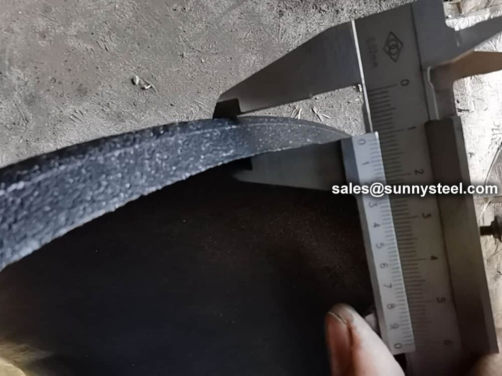
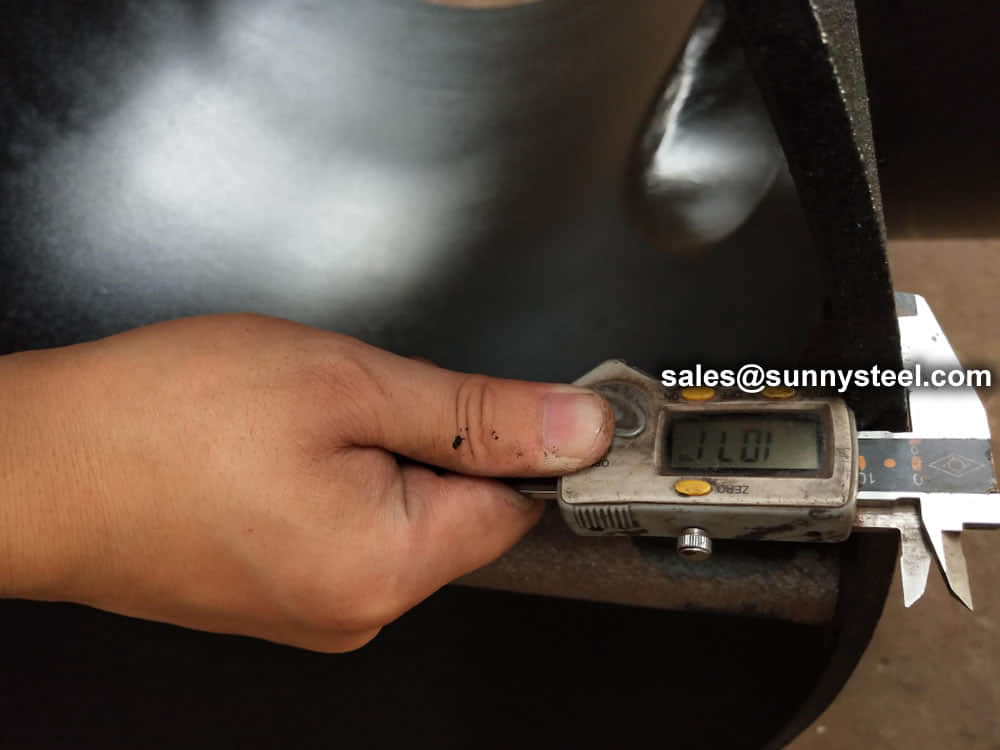
In the behavior, we make beveling after shot blasting, bevel ends are fully machined by advanced equipment Double Beveling Machine ensure the height, length, thickness, O.D. and I.D. are all qualified.
Welding Bevel acc. to
The ends of all buttweld fittings are bevelled, exceeding wall thickness 4 mm for austenitic stainless steel, or 5 mm for ferritic stainless steel. The shape of the bevel depending upon the actual wall thickness. This bevelled ends are needed to be able to make a “Butt weld”.
ASME B16.25 covers the preparation of buttwelding ends of piping components to be joined into a piping system by welding. It includes requirements for welding bevels, for external and internal shaping of heavy-wall components, and for preparation of internal ends (including dimensions and dimensional tolerances).
Our in-hourse R&D team developed bevel ends equipment are good using in thickness 2mm to 20mm pipe fittings, guarantee high efficiency and high quality.
| Nominal wall Thickness : t | End Preparation |
|---|---|
| t<5mm (for austenitic alloy steel | Cut square or slightly chamfer |
| t<4mm) | at manufacturer ' s option |
| 5<22mm (4<22mm)< td="" style="box-sizing: border-box;"><22mm)<><22mm |
Plain Bevel as in sketch ( a ) above |
| t>22mm | Compound Bevel as in sketch ( b ) above |
For the manufacturing process of all pipe fittings, forming is an indispensable process. Because the forming process of different products is different, it needs a long time.
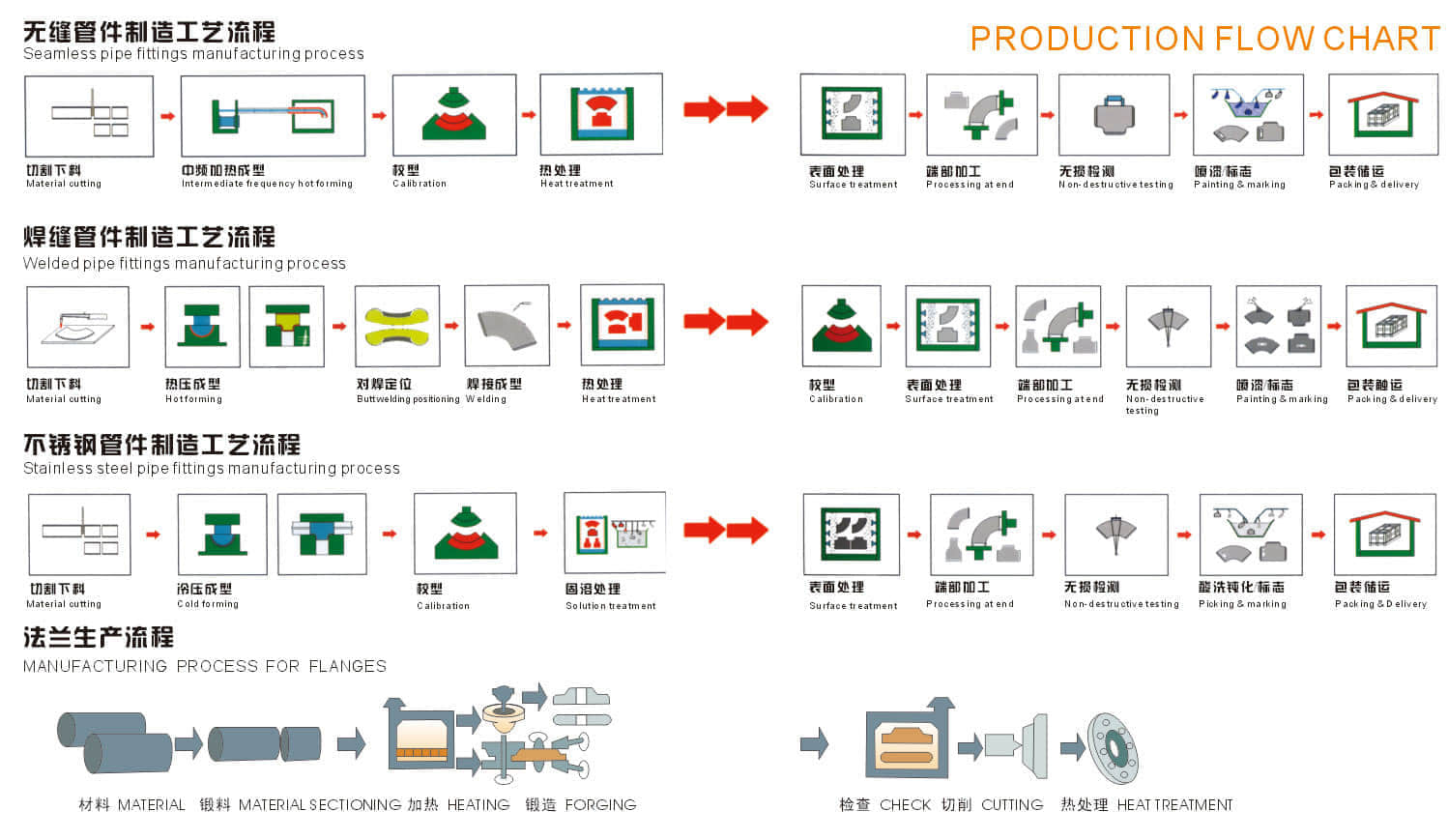
Heating
In order to meet the requirements of material deformation in the forming process, it is necessary to heat the blank when the tube is manufactured by hot forming method. The temperature usually depends on the material and heating process.
During the forming of hot pushing elbow or hot bending elbow, the medium frequency or high frequency induction heating method is usually used, and the flame heating method is also used. This kind of heating mode is continuous heating which is synchronous with the forming process of elbow or elbow. The tube blank is heated in motion and the forming process is completed.
When hot pressing elbow, hot pressing tee or forging are formed, the heating method of reverberatory furnace, flame heating, induction heating or electric furnace heating are usually adopted. This kind of heating is to first heat the tube blank to the required temperature, and then put it into the die for pressing or forging.
Welding
There are two kinds of pipe fittings with welding seam. One is the pipe fittings made of welded pipe. For the pipe fitting manufacturer, the forming process of welded pipe is basically the same as that of seamless pipe, and the forming process of pipe fitting does not include welding process; the other is that the pipe fitting manufacturer completes the welding process required for pipe fitting forming, such as the elbow formed by assembling and welding after single piece pressing The tee pipe is welded into tube blank after being rolled by steel plate drum, etc.
The commonly used welding methods of pipe fittings are manual arc welding, gas shielded welding and automatic welding.
Our factory guides the welding work according to the preparation of the welding procedure specification, and carries out the welding procedure qualification according to the corresponding specification requirements, so as to verify the correctness of the welding procedure specification and evaluate the welding ability of the welder.
One of the most common manufacturing methods for caps, where plate is cut out in a circle and formed by deep drawing.
Deep drawing is the manufacturing process of forming sheet metal stock, called blanks, into geometrical or irregular shapes that are more than half their diameters in depth. Deep drawing involves stretching the metal blank around a plug and then moving it into a moulding cutter called a die.
A drawing press can be used for forming sheet metal into different shapes and the finished shape depends on the final position that the blanks are pushed down in. The metal used in deep drawing must be malleable as well as resistant to stress and tension damage.
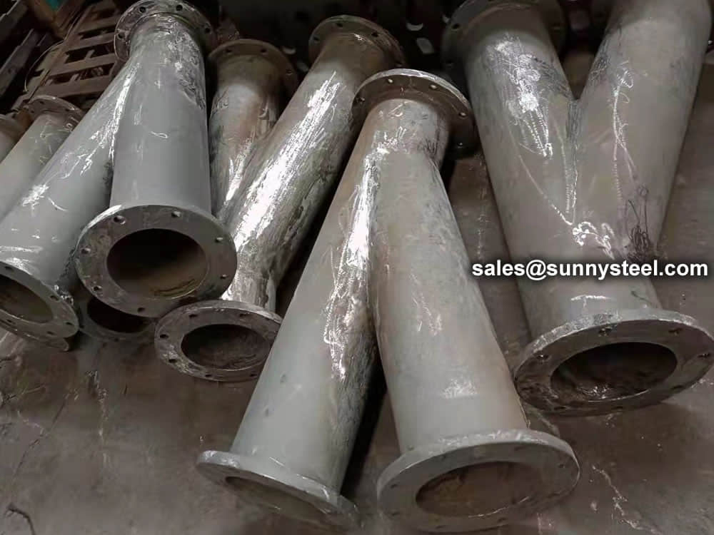
Pipe Tees are widely used in various commercial and industrial applications. Industrial applications include.
We are manufacturer of Reducing tee and supply high quality Reducing tee in both large and small quantities worldwide & offer you the best prices in the market.
Visual Inspection is conducted on fittings to check any surface imperfections. Both fittings body and weld are checked for any visible surface imperfections such as dents, die marks, porosity, undercuts, etc. Acceptance as per applicable standard.
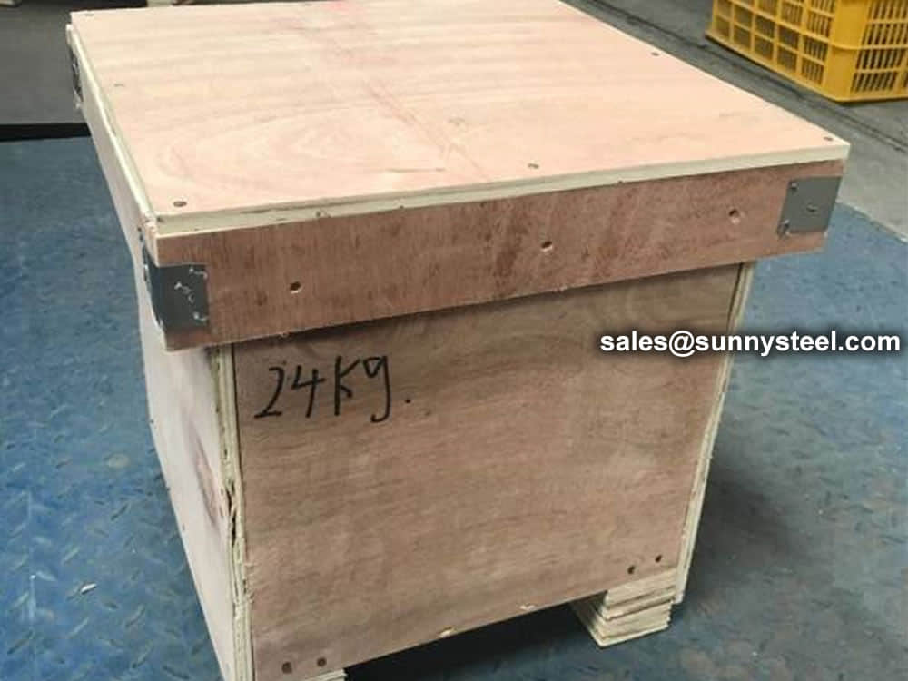
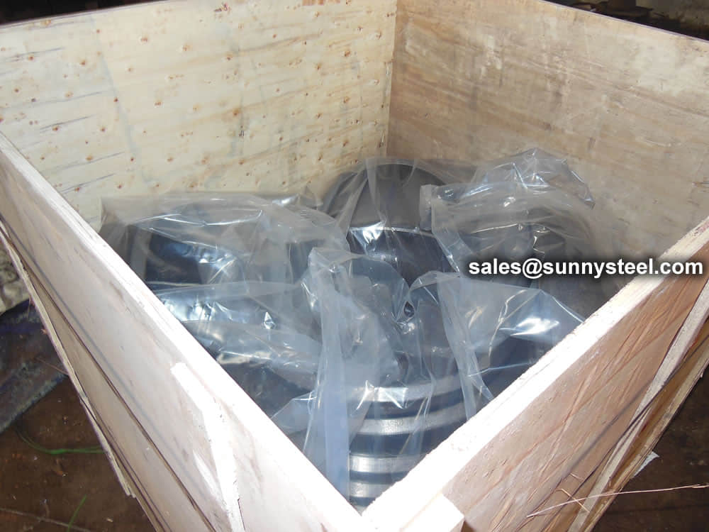
For packing of carbon steel flanges with painting,we would use the bubble wrap to protect the painting.For flanges without painting or oiled with long-term shipment,we would suggest client to use the anti-tarnish paper and plastic bag to prevent the rust.

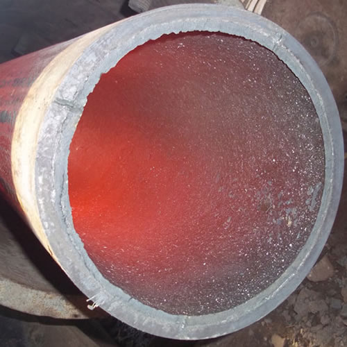
Ceramic lined pipe is made through self-propagating high-temperature synthesis (SHS) technique.
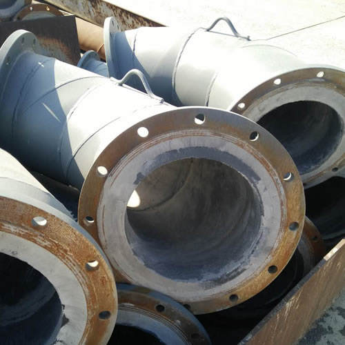
Cast basalt lined steel pipe is composed by lined with cast basalt pipe, outside steel pipe and cement mortar filling between the two layers.
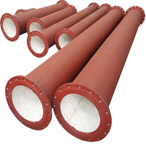
Ceramic tile lined pipes have very uniform coating of specially formulated ceramic material that is affixed to the inner of the pipe.
The material of the rare earth alloy wear-resistant pipe is ZG40CrMnMoNiSiRe, which is also the grade of rare earth alloy steel.
Tubes Erosion Shields are used to protect boiler tubing from the highly erosive effects of high temperatures and pressures thereby greatly extending tube life.
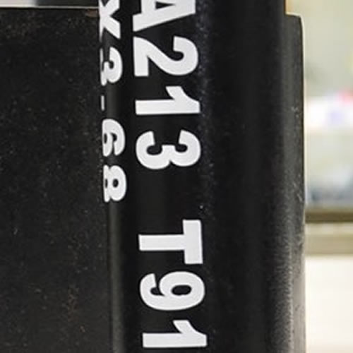
The ASTM A213 T91 seamless tubes are primarily used for boiler, superheater, and heat-exchanger.

When you partner with Sunny Steel, you can stop worrying about meeting deadlines thanks to our responsive and timely service. You'll also say goodbye to unnecessary shopping around. Instead, you'll get white glove service from an expert who understands your needs and can get you the materials you need quickly.