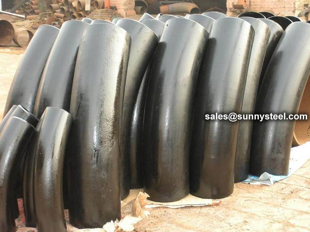

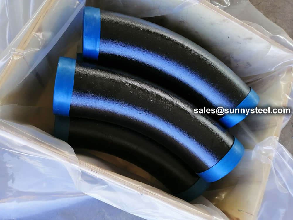
5D Bend Pipe
5D Bend Pipe - industrial steel pipe
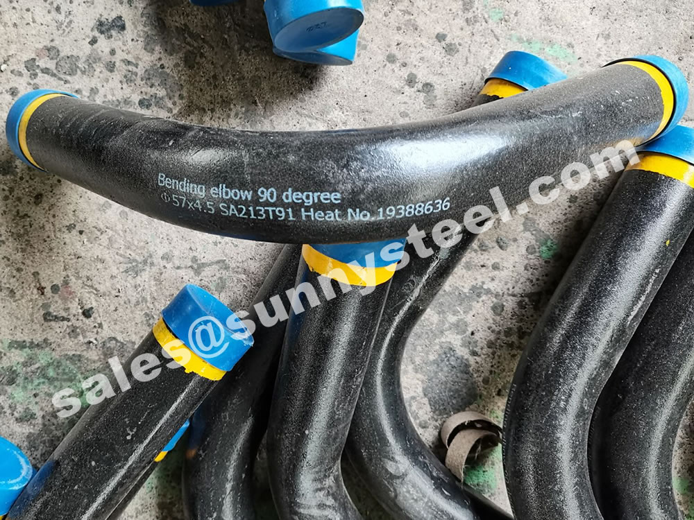
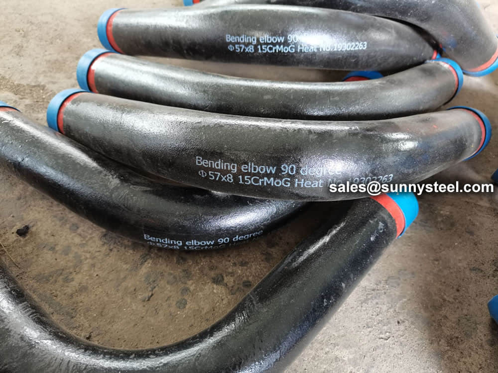
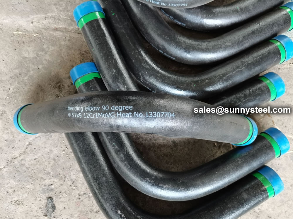
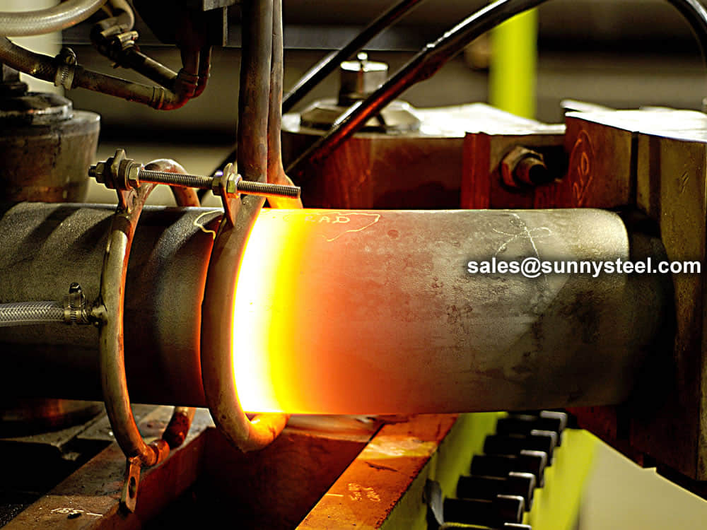
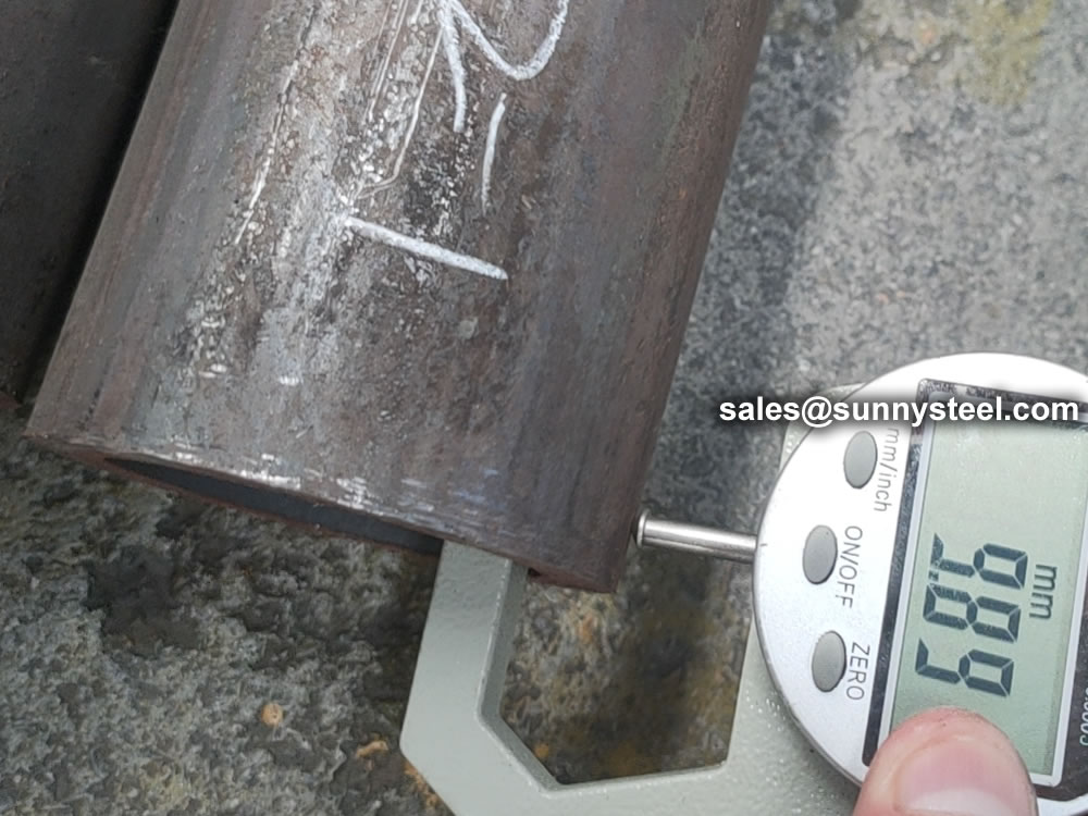
ASTM A210 Grade C bending is a process of forming the tubes into a desired shape or curvature using a bending machine or tool.
ASTM A210 Grade C is a standard specification for seamless medium-carbon steel boiler and superheater tubes. The bending of ASTM A210 Grade C tubes is a process of forming the tubes into a desired shape or curvature using a bending machine or tool. The tubes are heated to a specific temperature to make them pliable and then bent to the desired shape. The bending process is important in the manufacture of boiler and superheater tubes, as it allows for the tubes to be formed to fit the specific requirements of the application. The bending of ASTM A210 Grade C tubes should be performed in accordance with the relevant standards and guidelines to ensure that the tubes meet the required specifications and performance criteria.
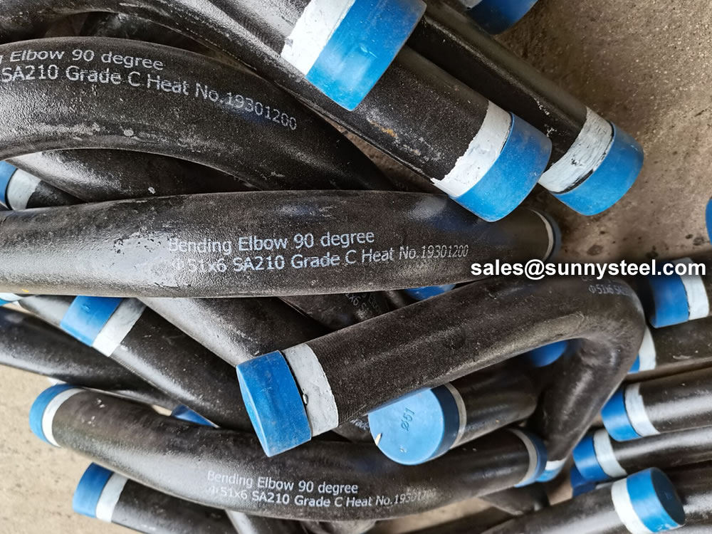
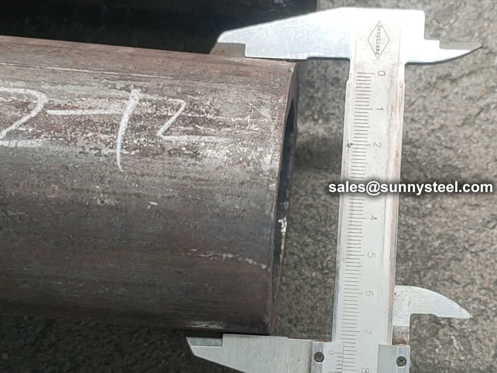
ASTM A210 Grade C specifies the requirements for seamless and welded carbon steel boiler tubes used in high-temperature applications. Bending these tubes is often necessary for fitting them into specific configurations or designs in boiler systems, superheaters, and heat exchangers.
Bending ASTM A210 Grade C tubes is a critical process in the fabrication of boiler and heat exchanger systems. Understanding material properties, employing the correct techniques, and adhering to industry standards are essential for achieving high-quality bends that meet performance requirements.
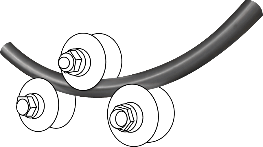
Pipe Bend Manufacturing Process
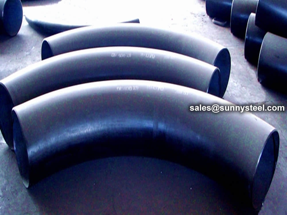
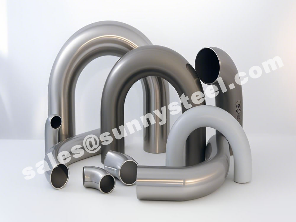
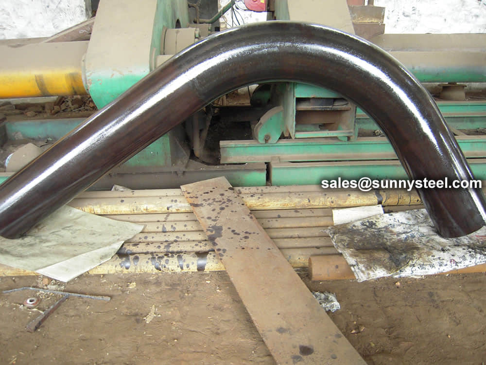
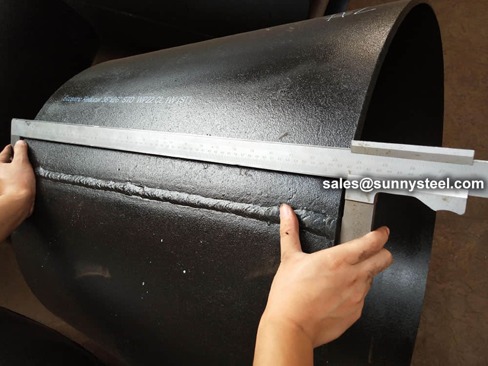
A pipe bend is a change in direction within a piping system, commonly referred to as an offset.
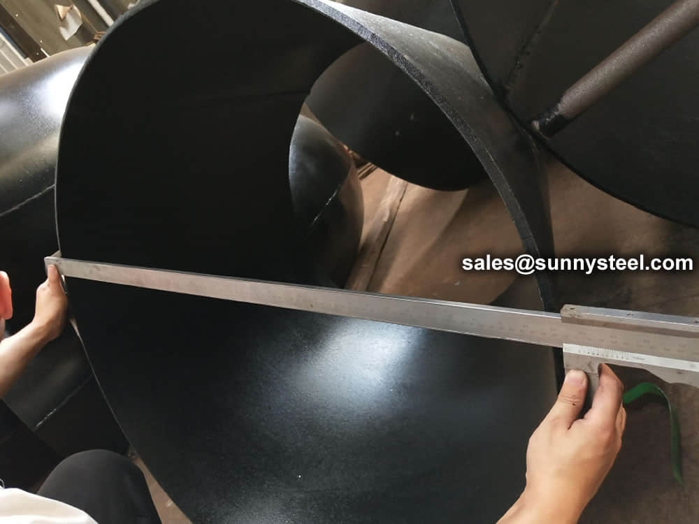
Pipe bends are usually custom manufactured using bending machines and are designed for specific routing requirements. Unlike elbows, bends provide a smoother flow path and reduced turbulence.
The most common bend radii used in industry are 1.5D, 3D, 5D and 10D. Long-radius bends generally provide lower pressure loss and improved flow performance.
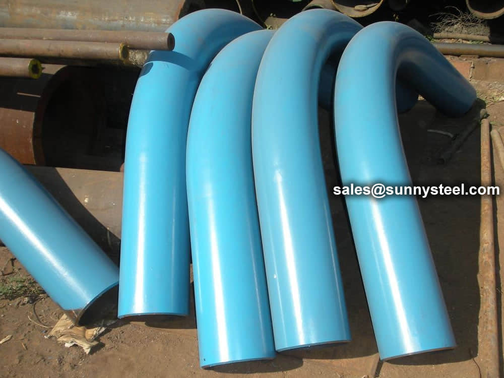
Pipe bends are widely used in chemical processing, oil & gas, power generation, shipbuilding, metallurgy and many other industrial applications.
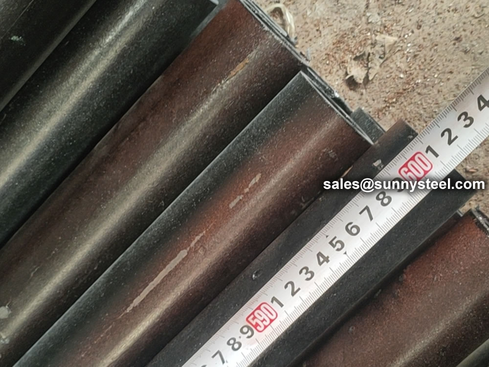
Bend pipes are available in various radii including 3D, 4D, 5D, 8D and 10D configurations. For example, the centerline radius of a 5D bend equals five times the nominal pipe diameter.
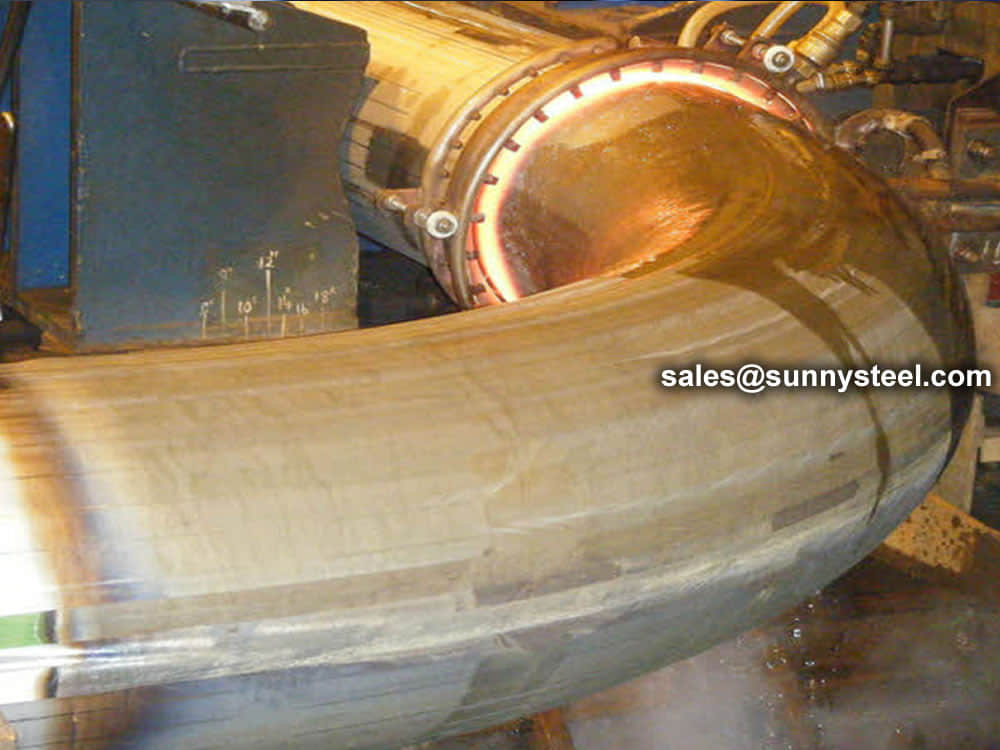
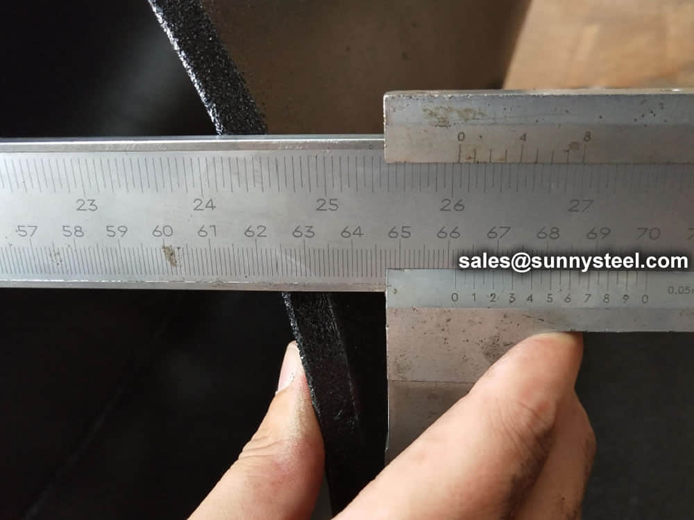
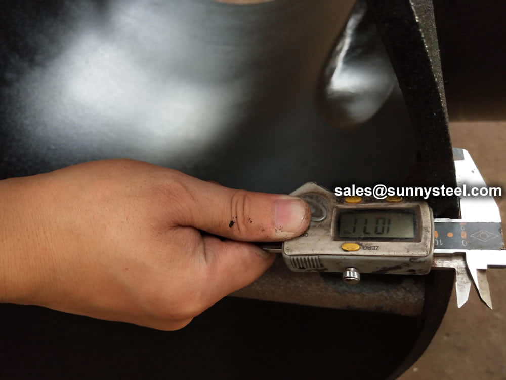
Modern pipe bending equipment enables highly accurate manufacturing with excellent dimensional control and repeatability.
| Item | Pipe Bend | Elbow |
|---|---|---|
| Radius | More than 2D | 1D to 2D |
| Flow Performance | Smoother Flow | Higher Turbulence |
| Pressure Drop | Lower | Higher |
| Manufacturing | Bending Process | Fitting Fabrication |
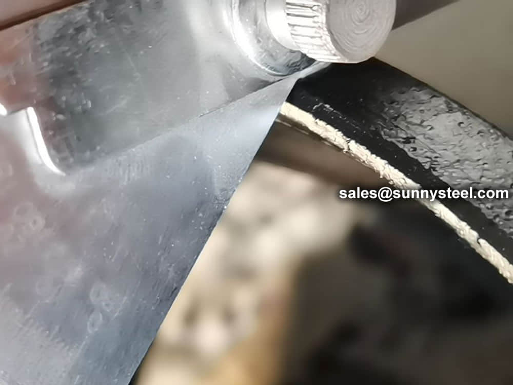
Uses localized induction heating to produce precise large-radius bends while maintaining material properties.
An economical bending method commonly used in fabrication workshops and exhaust manufacturing.
Suitable for producing very large radii in construction and structural applications.
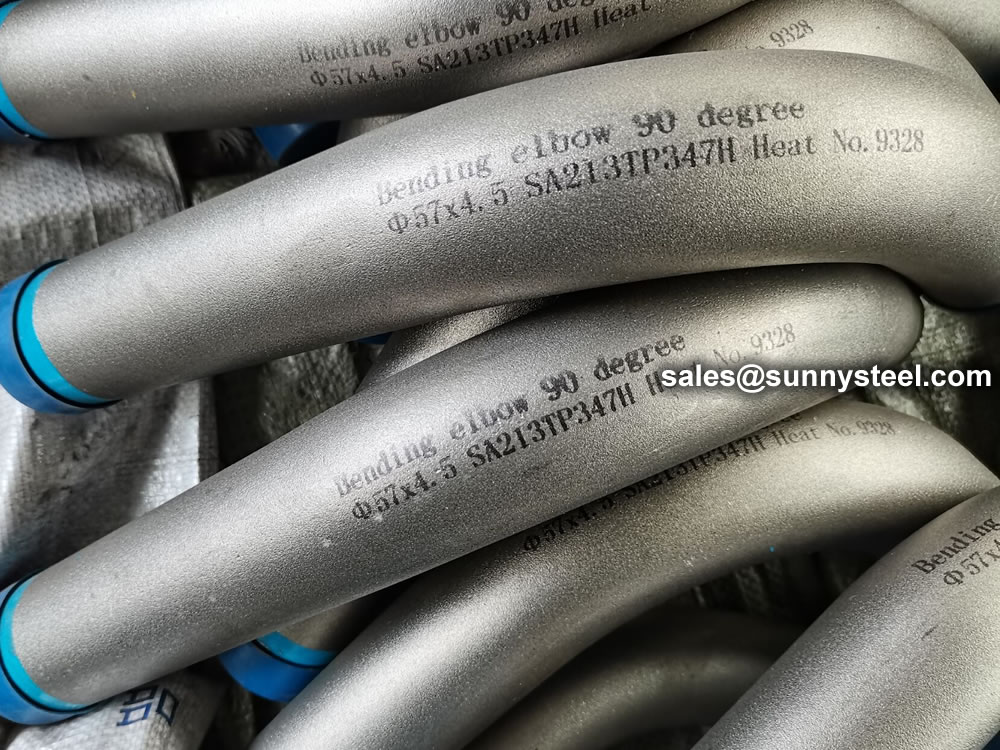
Produces high-quality bends with minimal deformation and excellent dimensional accuracy.
Frequently used when consistent diameter and superior surface finish are required.
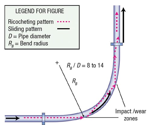
Typical flow patterns and wear zones in a long-radius bend.
Long-radius bends provide a gradual change in flow direction and help reduce particle impact and pipe wear.
Common bend classifications include:
| Dimensions | Standards |
|---|---|
| Outside Diameter | 1/2" – 36" |
| Bending Radius | 3D, 5D, 10D or Custom |
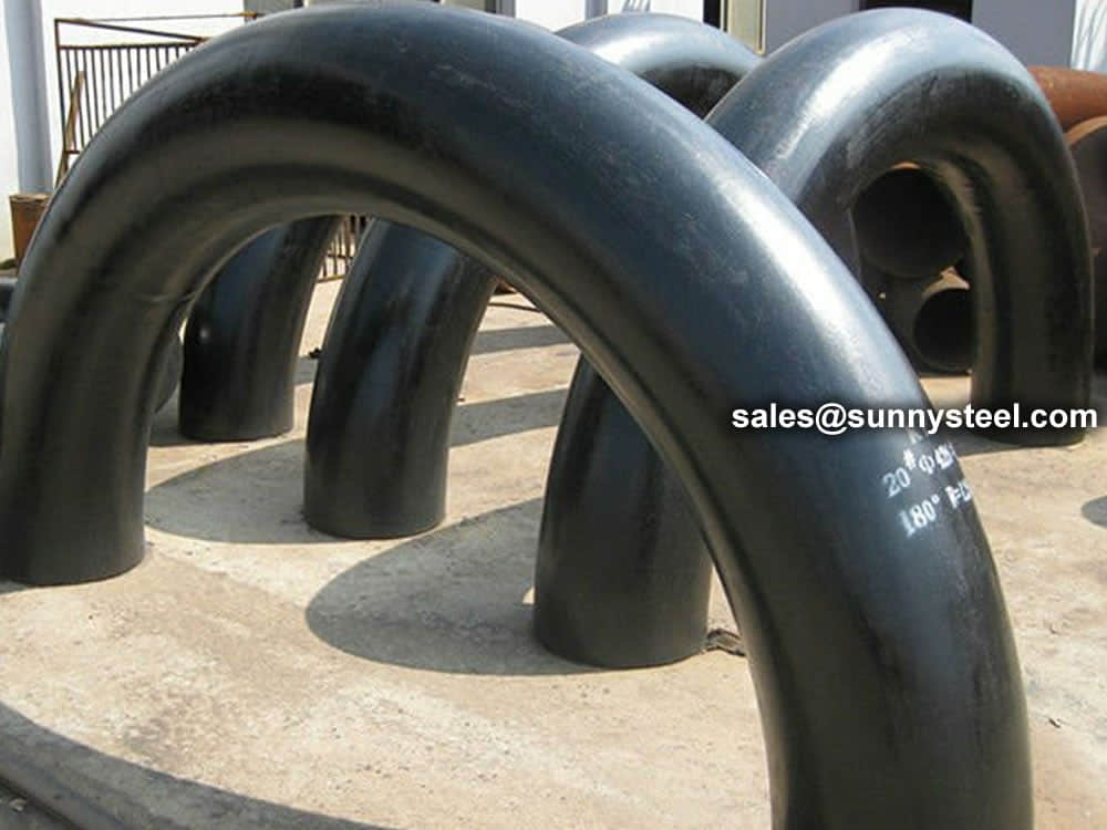
| Angle | Up to 180° |
| Wall Thickness | SCH5 to XXS |
| Materials | Carbon Steel, Stainless Steel, Alloy Steel, Duplex and Nickel Alloys |
The bend is used to change the direction of run of pipe.it advantage is can matach long distance transition requirements,so it is commonly that bends dimension according to customer design.
Formula:L = R x BL = Length of pipe requiredR = Radius of bendB = Constant from table used to find “L”L =30 x 1.5705 =47.115 in.or 47-1/8”
Standards accord to:
Pressure: SCH5 to SCH160
Bending radius(R): R=3D, 5D, 7D and 12D
Bending angle (θ):15°, 30°, 45°, 60°, 90°, 135°, 180°
Outer diamete(D): D≤1800mm
Wall thickness(T): T≤120mm
Straight Length (L): The length between two ends general from 300mm-1500mm
Example: Find the length of pipe required to make a 90 bend with a radius of 30"
| Nominal pipe | Outside Diameter at Bevel | Center to End | ||||
|---|---|---|---|---|---|---|
| DN size | D1 | D2 | C | M | ||
| Series A | Series B | Series A | Series B | |||
| 20×15 | 26.9 | 25 | 21.3 | 18 | 29 | 29 |
| 25×20 | 33.7 | 32 | 26.9 | 25 | 38 | 38 |
| 25×15 | 33.7 | 32 | 21.3 | 18 | 38 | 38 |
| 32×25 | 42.4 | 38 | 33.7 | 32 | 48 | 48 |
| 32×20 | 42.4 | 38 | 26.9 | 25 | 48 | 48 |
| 32×15 | 42.4 | 38 | 21.3 | 18 | 48 | 48 |
| 40×32 | 48.3 | 45 | 42.4 | 38 | 57 | 57 |
| 40×25 | 48.3 | 45 | 33.7 | 32 | 57 | 57 |
| 40×20 | 48.3 | 45 | 26.7 | 25 | 57 | 57 |
| 40×15 | 48.3 | 45 | 21.3 | 18 | 57 | 57 |
| 50×40 | 60.3 | 57 | 48.3 | 45 | 64 | 60 |
| 50×32 | 60.3 | 57 | 42.4 | 38 | 64 | 57 |
| 50×25 | 60.3 | 57 | 33.7 | 32 | 64 | 51 |
| 50×20 | 60.3 | 57 | 26.9 | 25 | 64 | 44 |
| 65×50 | 76.1(73) | 76 | 60.3 | 57 | 76 | 70 |
| 65×40 | 76.1(73) | 76 | 48.3 | 45 | 76 | 67 |
| 65×32 | 76.1(73) | 76 | 42.4 | 38 | 76 | 64 |
| 65×25 | 76.1(73) | 76 | 33.7 | 32 | 76 | 57 |
| 80×65 | 88.9 | 89 | 76.1(73) | 76 | 86 | 83 |
| 80×50 | 88.9 | 89 | 60.3 | 57 | 86 | 76 |
| 80×40 | 88.9 | 89 | 48.3 | 45 | 86 | 73 |
| 80×32 | 88.9 | 89 | 42.4 | 38 | 86 | 70 |
| 90×80 | 101.6 | - | 88.9 | - | 95 | 92 |
| 90×65 | 101.6 | - | 76.1(73) | - | 95 | 89 |
| 90×50 | 101.6 | - | 60.3 | - | 95 | 83 |
| 90×40 | 101.6 | - | 48.3 | - | 95 | 79 |
| 100×90 | 114.3 | - | 101.6 | - | 105 | 102 |
| 100×80 | 114.3 | 108 | 88.9 | 89 | 105 | 98 |
| 100×65 | 114.3 | 108 | 76.1(73) | 76 | 105 | 95 |
| 100×50 | 114.3 | 108 | 60.3 | 57 | 105 | 89 |
| 100×40 | 114.3 | 108 | 48.3 | 45 | 105 | 86 |
| 125×100 | 139.7 | 133 | 114.3 | 108 | 124 | 117 |
| 125×90 | 139.7 | - | 101.6 | - | 124 | 114 |
| 125×80 | 139.7 | 133 | 88.9 | 89 | 124 | 111 |
| 125×65 | 139.7 | 133 | 76.1(73) | 76 | 124 | 108 |
| 125×50 | 133 | 60.3 | 57 | 124 | 105 | |
| 150×125 | 168.3 | 159 | 139.7 | 133 | 143 | 137 |
| 150×100 | 168.3 | 159 | 114.3 | 108 | 143 | 130 |
| 150×90 | 168.3 | - | 101.6 | - | 143 | 127 |
| 150×80 | 168.3 | 159 | 88.9 | 89 | 143 | 124 |
| 150×65 | 168.3 | 159 | 76.1(73) | 76 | 143 | 121 |
| 200×150 | 219.1 | 219 | 168.3 | 159 | 178 | 168 |
| 200×125 | 219.1 | 219 | 139.7 | 133 | 178 | 162 |
| 200×100 | 219.1 | 219 | 114.3 | 108 | 178 | 156 |
| 200×90 | 219.1 | - | 101.6 | - | 178 | 152 |
| 200×200 | 273 | 273 | 219.1 | 219 | 216 | 208 |
| 200×150 | 273 | 273 | 168.3 | 159 | 216 | 194 |
| 200×125 | 273 | 273 | 139.7 | 133 | 216 | 191 |
| 200×100 | 273 | 273 | 114.3 | 108 | 216 | 184 |
| 300×250 | 323.9 | 325 | 273 | 273 | 254 | 241 |
| 300×200 | 323.9 | 325 | 219.1 | 219 | 254 | 229 |
| 300×150 | 323.9 | 325 | 168.3 | 159 | 254 | 219 |
| 300×125 | 323.9 | 325 | 139.7 | 133 | 254 | 216 |
| 350×300 | 355.6 | 377 | 323.9 | 325 | 279 | 270 |
| 350×250 | 355.6 | 377 | 273 | 273 | 279 | 257 |
| 350×200 | 355.6 | 377 | 219.1 | 219 | 279 | 248 |
| 350×150 | 355.6 | 377 | 168.3 | 159 | 279 | 238 |
| 400×350 | 406.4 | 426 | 355.6 | 377 | 305 | 305 |
| 400×300 | 406.4 | 426 | 323.9 | 325 | 305 | 295 |
| 400×250 | 406.4 | 426 | 273 | 273 | 305 | 283 |
| 400×200 | 406.4 | 426 | 219.1 | 219 | 305 | 273 |
| 400×150 | 406.4 | 426 | 168.3 | 159 | 305 | 264 |
| 450×400 | 457.2 | 478 | 406.4 | 426 | 343 | 330 |
| 450×350 | 457.2 | 478 | 355.6 | 377 | 343 | 330 |
| 450×300 | 457.2 | 478 | 323.9 | 325 | 343 | 321 |
| 450×250 | 457.2 | 478 | 273 | 273 | 343 | 308 |
| 450×200 | 457.2 | 478 | 219.1 | 219 | 343 | 298 |
| 500×450 | 508 | 529 | 457.2 | 478 | 381 | 368 |
| 500×100 | 508 | 529 | 406.4 | 426 | 381 | 356 |
| 500×350 | 508 | 529 | 355.6 | 377 | 381 | 356 |
| 500×300 | 508 | 529 | 323.9 | 325 | 381 | 346 |
| 500×250 | 508 | 529 | 273 | 273 | 381 | 333 |
| 500×200 | 508 | 529 | 219.1 | 219 | 381 | 324 |
| 550×500 | 559 | - | 508 | - | 419 | 406 |
| 550×450 | 559 | - | 457 | - | 419 | 394 |
| 550×400 | 559 | - | 406 | - | 419 | 381 |
| 600×550 | 610 | - | 559 | - | 432 | 432 |
| 600×550 | 610 | 630 | 508 | 530 | 432 | 432 |
| 600×450 | 610 | 630 | 457 | 480 | 432 | 419 |
| 650×600 | 660 | - | 610 | - | 495 | 483 |
| 650×550 | 660 | - | 559 | - | 495 | 470 |
| 650×500 | 660 | - | 508 | - | 495 | 457 |
| 700×650 | 711 | - | 660 | - | 521 | 521 |
| 700×600 | 711 | 720 | 610 | 630 | 521 | 508 |
| 700×550 | 711 | - | 559 | - | 521 | 495 |
| 750×700 | 762 | - | 711 | - | 559 | 546 |
| 750×650 | 762 | - | 660 | - | 559 | 546 |
| 750×600 | 762 | - | 610 | - | 559 | 533 |
| 800×750 | 813 | - | 762 | - | 597 | 584 |
| 800×700 | 813 | 820 | 711 | 720 | 597 | 572 |
| 800×650 | 813 | - | 660 | - | 597 | 572 |
| 850×800 | 864 | - | 813 | - | 635 | 622 |
| 850×750 | 864 | - | 762 | - | 635 | 610 |
| 850×700 | 864 | - | 711 | - | 635 | 597 |
| 900×850 | 914 | - | 864 | - | 673 | 660 |
| 900×800 | 914 | 920 | 813 | 820 | 673 | 648 |
| 900×750 | 914 | - | 762 | - | 673 | 635 |
| 950×900 | 965 | - | 914 | - | 711 | 711 |
| 950×850 | 965 | - | 864 | - | 711 | 698 |
| 950×800 | 965 | - | 813 | - | 711 | 686 |
| 1000×950 | 1016 | - | 965 | - | 749 | 749 |
| 1000×900 | 1016 | 1020 | 914 | 920 | 749 | 737 |
| 1000×8500 | 1016 | - | 864 | - | 749 | 724 |
| 1000×1000 | 1067 | - | 1016 | - | 762 | 711 |
| 1050×950 | 1067 | - | 965 | - | 762 | 711 |
| 1050×900 | 1067 | - | 914 | - | 762 | 711 |
| 1100×1050 | 1118 | - | 1067 | - | 813 | 762 |
| 1100×1000 | 1118 | 1120 | 1016 | 1020 | 813 | 749 |
| 1100×950 | 1118 | - | 965 | - | 813 | 737 |
| 1150×1100 | 1168 | - | 1118 | - | 851 | 800 |
| 1150×1050 | 1168 | - | 1067 | - | 851 | 787 |
| 1150×1000 | 1168 | - | 1016 | - | 851 | 775 |
| 1200×1150 | 1220 | - | 1168 | - | 889 | 838 |
| 1200×1100 | 1220 | 1220 | 1118 | 1120 | 889 | 838 |
| 1200×1050 | 1220 | - | 1067 | - | 889 | 813 |
Just before the final delivery, our merchandise are stringently checked by a team of quality analyzers on varied parameters, which guarantee their flawlessness and durability. In addition, clients can avail these goods from us at competitive rates.
Pipe bends play a vital role in flow control systems, allowing the smooth and efficient redirection of fluids and gases. These components are designed to change the direction of piping systems, allowing the fluid or gas to flow around obstacles or corners with minimal turbulence or pressure loss. By minimising friction and pressure drop, pipe bends help maintain optimum flow rates, reduce energy consumption and improve overall system performance.

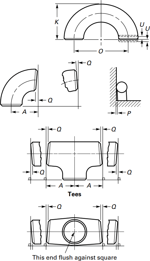
ASME B16.9 Standard covers overall dimensions, tolerances,ratings, testing, and markings for factory-made wrought buttwelding fittings in sizes NPS 1⁄2 through NPS 48 (DN 15 through DN 1200).
Download PDF| Nominal | Outside Diameter | 90° Elbows | 45° Elbows | 180° Returns | ||||
|---|---|---|---|---|---|---|---|---|
| Pipe Size |
Long Radius | Short Radius | Long Radius | Long Radius | ||||
| (inches) | (mm) | (inches) | Center to Face | Center to Face | Center to Face | Radius | Center to Center | Back to face |
| (inches) | (inches) | (inches) | (inches) | (inches) | (inches) | |||
| 1/2 | 21.3 | 0.84 | 1.5 | – | 5/8 | 2 | 1.875 | |
| 3/4 | 26.7 | 1.05 | 1.125 | – | 7/16 | 2.25 | 1.6875 | |
| 1 | 33.4 | 1.315 | 1.5 | 1 | 7/8 | 3 | 2.1875 | |
| 1.25 | 42.2 | 1.66 | 1.875 | 1.25 | 1 | 3.75 | 2.75 | |
| 1.5 | 48.3 | 1.9 | 2.25 | 1.5 | 1.125 | 3 | 4.5 | 3.25 |
| 2 | 60.3 | 2.375 | 3 | 2 | 1.375 | 4 | 6 | 4.1875 |
| 2.5 | 73 | 2.875 | 3.75 | 2.5 | 1.75 | 5 | 7.5 | 5.1875 |
| 3 | 88.9 | 3.5 | 4.5 | 3 | 2 | 6 | 9 | 6.25 |
| 3.5 | 101.6 | 4 | 5.25 | 3.5 | 2.25 | 7 | 10.5 | 7.25 |
| 4 | 114.3 | 4.5 | 6 | 4 | 2.5 | 8 | 12 | 8.25 |
| 5 | 141.3 | 5.563 | 7.5 | 5 | 3.125 | 10 | 15 | 10.3125 |
| 6 | 168.3 | 6.625 | 9 | 6 | 3.75 | 12 | 18 | 12.3125 |
| 8 | 219.1 | 8.625 | 12 | 8 | 5 | 12 | 24 | 16.3125 |
| 10 | 273.1 | 10.75 | 15 | 10 | 6.25 | 15 | 30 | 20.375 |
| 12 | 323.9 | 12.75 | 18 | 12 | 7.5 | 18 | 36 | 24.375 |
| NOMINAL PIPE SIZE NPS | ANGULARITY TOLERANCES | ANGULARITY TOLERANCES |
|---|---|---|
| Size | Off Angle Q | Off Plane P |
| ½ to 4 | 0.03 | 0.06 |
| 5 to 8 | 0.06 | 0.12 |
| 10 to 12 | 0.09 | 0.19 |
| 14 to 16 | 0.09 | 0.25 |
| 18 to 24 | 0.12 | 0.38 |
| 26 to 30 | 0.19 | 0.38 |
| 32 to 42 | 0.19 | 0.5 |
| 44 to 48 | 0.18 | 0.75 |
All dimensions are given in inches. Tolerances are equal plus and minus except as noted.
The ASME B16.9 pipe fittings can be used under the jurisdiction of the ASME Boiler & Pressure Vessel Code (BPVC) as well as the ASME Code for pressure piping. Referencing pressure ratings of flanges per ASME B16.5, they can be designated as Classes 150, 300, 600, 900, 1500 and 2500. The allowable pressure ratings for ASME B16.9 pipe fittings may be calculated as for straight seamless pipe of equivalent material in accordance with the rules established in the applicable sections of ASME B31 Code for pressure piping.
The design of butt welding pipe fittings made to ASME B16.9 shall be established by one of the following methods: (a) mathematical analyses contained in pressure vessel or piping codes; (b) proof testing; (c) experimental stress analysis with hydrostatic testing to validate experimental results; (d) detailed stress analysis with results evaluation.
Generally, ASME B16.9 pipe fittings shall be marked to show the following details: “trademark + material grade + wall thickness + size + heat number”. For example, “M ASTM A234 WP5 SCH80 6″ 385“. When steel stamps are used, care shall be taken so that
the marking is not deep enough or sharp enough to cause cracks or to reduce the wall thickness of the fitting below the minimum allowed.
The ASME B16.9 fittings may be made from an extensive range of mateirals covering (1) carbon and low-alloy steels in accordance with ASTM A234 and ASTM A420; (2) austenitic and duplex stainless steels in accordance with ASTM A403 and ASTM A815; (3) nickel alloys in accordance with ASTM B366; (4) aluminum alloys in accordance with ASTM B361; and (5) titanium alloys in accordance with ASTM B363.
Sizes 1/2″ – 48″


1.1 This specification2 covers minimum-wall-thickness, seamless medium-carbon steel, boiler tubes and boiler flues, including safe ends (see Note 1), arch and stay tubes, and superheater tubes.
NOTE 1: This type is not suitable for safe ending by forge welding.
1.2 The tubing sizes and thicknesses usually furnished to this specification are 1/2 in. to 5 in. [12.7 to 127 mm] in outside diameter and 0.035 to 0.500 in. [0.9 to 12.7 mm], inclusive, in minimum wall thickness. Tubing having other dimensions may be furnished, provided such tubes comply with all other requirements of this specification.
1.3 Mechanical property requirements do not apply to tubing smaller than 1/8 in. [3.2 mm] in inside diameter or 0.015 in. [0.4 mm] in thickness.
1.4 This specification covers grades A-1 and C of Seamless Medium-Carbon Boiler and Superheater Tubes with different chemical and tensile requirements. (Table 1, Table 3, and Section 11.)
1.5 The values stated in either inch-pound units or SI units are to be regarded separately as standard. Within the text, the SI units are shown in brackets. The values stated in each system are not exact equivalents; therefore, each system must be used independently of the other. Combining values from the two systems may result in nonconformance with the specification. The inch-pound units shall apply unless the "M" designation of this specification is specified in the order.
1.6 This international standard was developed in accordance with internationally recognized principles on standardization established in the Decision on Principles for the Development of International Standards, Guides and Recommendations issued by the World Trade Organization Technical Barriers to Trade (TBT) Committee.
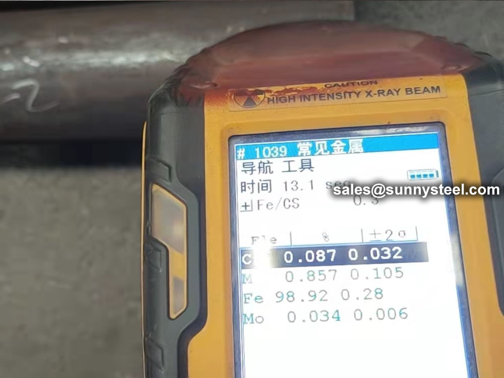
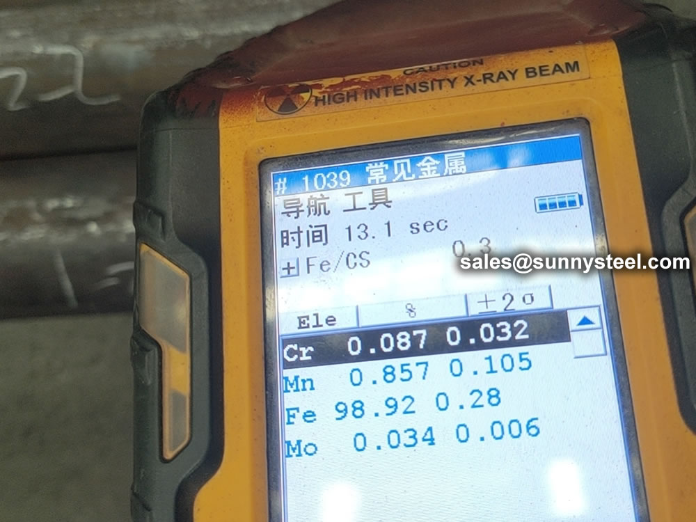
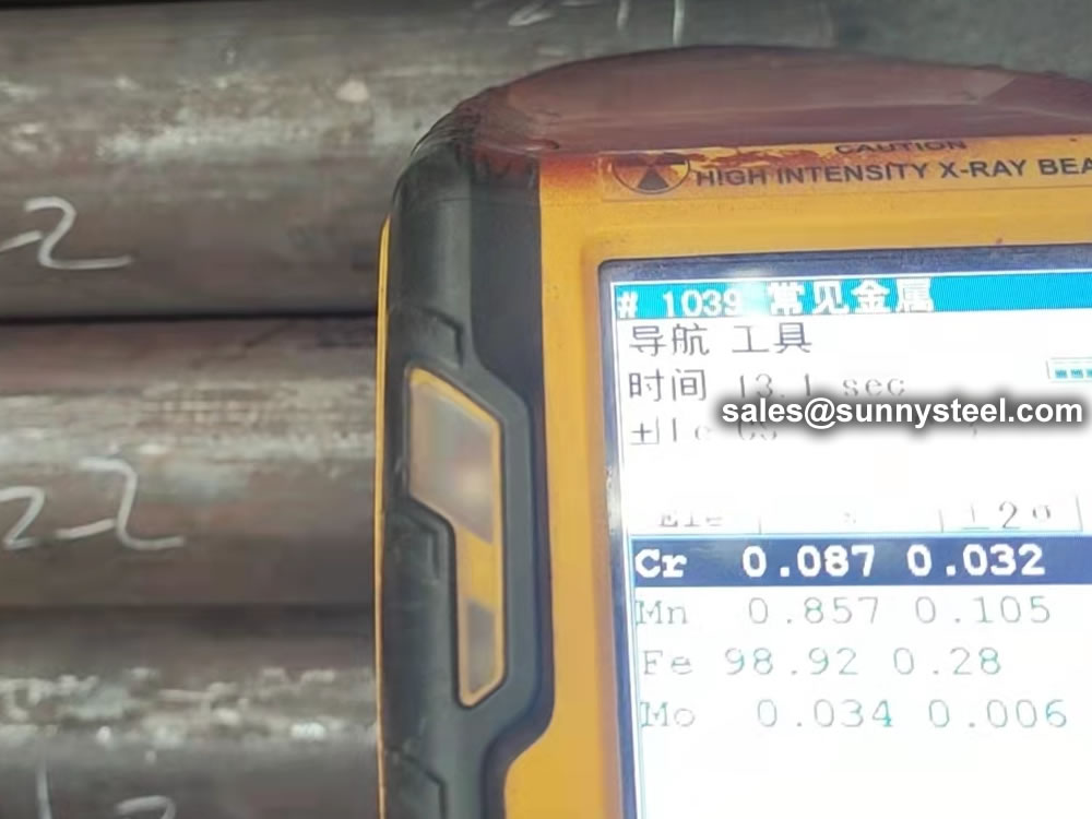
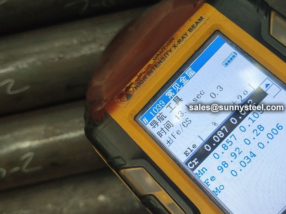
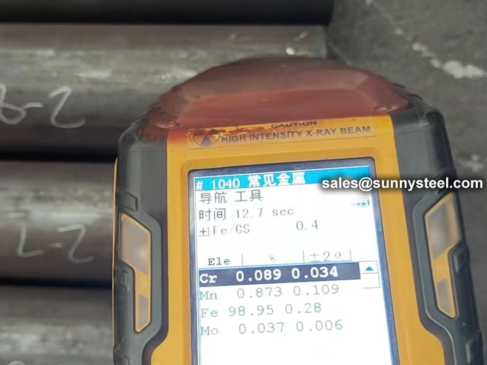
| Steel Grade | C | Si | Mn | S | P |
|---|---|---|---|---|---|
| A210 A1/ SA-210A1 | ≤0.27 | ≥0.10 | ≤0.93 | 0.020 | 0.025 |
| A210C/ SA-210C | ≤0.35 | ≥0.10 | 0.29-1.06 | 0.020 | 0.025 |
| Grade | Tensile strength (Mpa) |
Yield point(Mpa) not less than |
Elongation(%) not less than |
Impact(J) not less than |
Hardness not less than |
|---|---|---|---|---|---|
| A210 A1/ SA-210A1 | ≥415 | 255 | " | 79HRB | |
| A210C/ SA-210C | ≥485 | 275 | " | 89HRB |
| Hot rolled | Outside Diameter, mm | Tolerance, mm |
|---|---|---|
| OD≤101.6 | +0.4/-0.8 | |
| 101.6<OD≤127 | +0.4/-1.2 | |
| Cold Drawn | Outside Diameter, mm | Tolerance, mm |
| OD<25.4 | ±0.10 | |
| 25.4≤OD≤38.1 | ±0.15 | |
| 38.1<OD<50.8 | ±0.20 | |
| 50.8≤OD<63.5 | ±0.25 | |
| 63.5≤OD<76.2 | ±0.30 | |
| 76.2≤OD≤101.6 | ±0.38 | |
| 101.6<OD≤127 | +0.38/-0.64 |
| Hot rolled | Outside Diameter, mm | Tolerance, % |
|---|---|---|
| OD≤101.6, WT≤2.4 | +40/-0 | |
| OD≤101.6, 2.4<WT≤3.8 | +35/-0 | |
| OD≤101.6, 3.8<WT≤4.6 | +33/-0 | |
| OD≤101.6, WT>4.6 | +28/-0 | |
| OD>101.6, 2.4<WT≤3.8 | +35/-0 | |
| OD>101.6, 3.8<WT≤4.6 | +33/-0 | |
| OD>101.6, WT>4.6 | +28/-0 | |
| Cold Drawn | Outside Diameter , mm | Tolerance, % |
| OD≤38.1 | +20/-0 | |
| OD>38.1 | +22/-0 |
| Method of Manufacture |
Outside Diameter, in. [mm] |
Cut Length,in. [mm] | |
|---|---|---|---|
| Over | Under | ||
| Seamless, hot-finished | All sizes | 3 ⁄ 16 [5] | 0 [0] |
| Seamless, cold-finished | Under 2 [50.8] | 1 ⁄ 8 [3] | 0 [0] |
| 2 [50.8] and over | 3 ⁄ 16 [5] | 0 [0] | |
| 2 [50.8] and over | 3 ⁄ 16 [5] | 0 [0] | |
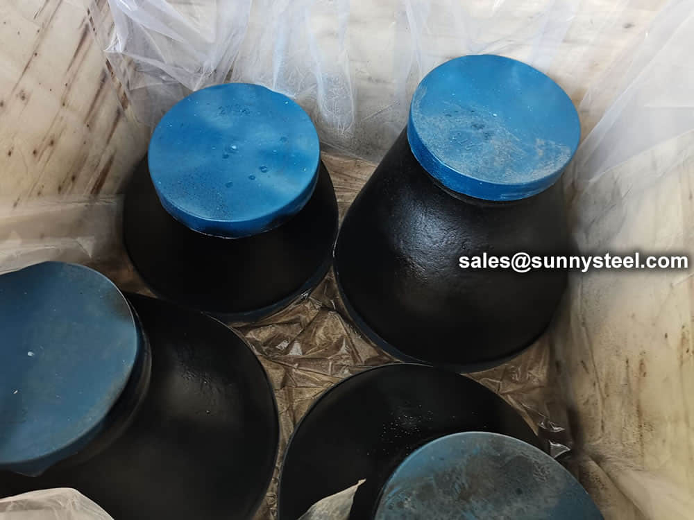
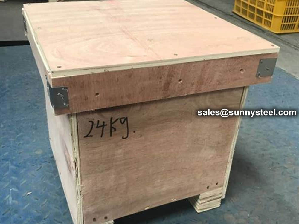
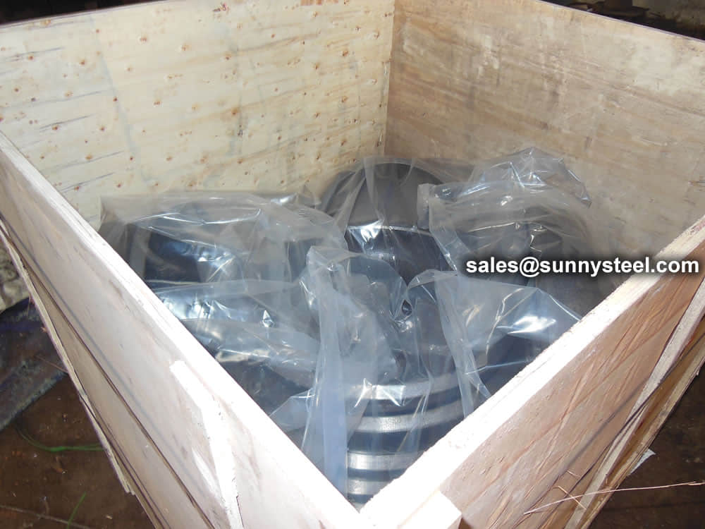
Both ends of each crate will indicate the order no., heat no., dimensions, weight and bundles or as requested.
(1)Tension Test—One tension test shall be made on a specimen for lots of not more than 50 tubes. Tension tests shall be made on specimens from two tubes for lots of more than 50 tubes.
(2)Flattening Test—One flattening test shall be made on specimens from each end of one finished tube from each lot.
(3)Flaring Test—One flaring test shall be made on speci- mens from each end of the one finished tube from each lot.
(4)Hardness Test—Brinell or Rockwell hardness tests shall be made on specimens from two tubes from each lot.
(5)Hydrostatic or Nondestructive Electric Test—Each tube shall be subjected to the hydrostatic.
One flattening test shall be made on specimens from each end of one finished tube from each lot, but not the one used for the flaring test. Tears or breaks occurring at the 12 or 6 o’clock positions on Grade C tubing with sizes of 2.375 in. [60.3 mm] in outside diameter and smaller shall not be considered a basis for rejection.
One flaring test shall be made on specie- men from each end of the one finished tube from each lot, but not the one used for the flattening test.
Orders for ASTM A210 / A210M, ASME SA210 should include the following, as required, to describe the desired material adequately:
Pipe fitting dimensions are in either metric or Standard English.
Because pipe fitting covers Pipe Fitting Dimensions several aspects, only the most common pipe fitting sizes can be given here. The most applied version is the 90° long radius and the 45° elbow, while the 90° short radius elbow is applied if there is too little space. The function of a 180° elbow is to change direction of flow through 180°. Both, the LR and the SR types have a center to center dimension double the matching 90° elbows. These fittings will generally be used in furnesses or other heating or cooling units.
Some of the standards that apply to buttwelded fittings are listed below. Many organizations such as ASME, ASTM, ISO, MSS, etc. have very well developed standards and specifications for buttwelded fittings. It is always up to the designer to ensure that they are following the applicable standard and company specification, if available, during the design process.
Some widely used pipe fitting standards are as follows:
This is one of the reputed organizations in the world developing codes and standards.
The schedule number for pipe fitting starts from ASME/ANSI B16. The various classifications of ASME/ANSI B16 standards for different pipe fittings are as follows:
This is one of the largest voluntary standards development organizations in the world. It was originally known as the American Society for Testing and Materials (ASTM).
AWWA About – Established in 1881, the American Water Works Association is the largest nonprofit, scientific and educational association dedicated to managing and treating water, the world’s most important resource.
ANSI is a private, non-profit organization. Its main function is to administer and coordinate the U.S. voluntary standardization and conformity assessment system. It provides a forum for development of American national standards. ANSI assigns "schedule numbers". These numbers classify wall thicknesses for different pressure uses.
The Manufacturers Standardization Society (MSS) of the Valve and Fittings Industry is a non-profit technical association organized for development and improvement of industry, national and international codes and standards for: Valves, Valve Actuators, Valve Modification, Pipe Fittings, Pipe Hangers, Pipe Supports, Flanges and Associated Seals
Piping codes imply the requirements of design, fabrication, use of materials, tests and inspection of various pipe and piping system. It has a limited jurisdiction defined by the code. On the other hand, piping standards imply application design and construction rules and requirements for pipe fittings like adapters, flanges, sleeves, elbows, union, tees, valves etc. Like a code, it also has a limited scope defined by the standard.
"Standards" on pipe fittings are based on certain factors like as follows:
BSP is the U.K. standard for pipe fittings. This refers to a family of standard screw thread types for interconnecting and sealing pipe ends by mating an external (male) with an internal (female) thread. This has been adopted internationally. It is also known as British Standard Pipe Taper threads (BSPT )or British Standard Pipe Parallel (Straight) threads (BSPP ). While the BSPT achieves pressure tight joints by the threads alone, the BSPP requires a sealing ring.
This is the Japanese industrial standards or the standards used for industrial activities in Japan for pipe, tube and fittings and published through Japanese Standards Associations.
National Pipe Thread is a U.S. standard straight (NPS) threads or for tapered (NPT) threads. This is the most popular US standard for pipe fittings. NPT fittings are based on the internal diameter (ID) of the pipe fitting.
We are manufacturer of Flange bolts & Nuts and supply high quality
The AN standard was originally designed for the U.S. Military. Whenever, a pipe fitting is AN fittings, it means that the fittings are measured on the outside diameter of the fittings, that is, in 1/16 inch increments.
For example, an AN 4 fitting means a fitting with an external diameter of approximately 4/16″ or ¼”. It is to be noted that approximation is important because AN external diameter is not a direct fit with an equivalent NPT thread.
Dash size is the standard used to refer to the inside diameter of a hose. This indicates the size by a two digit number which represents the relative ID in sixteenths of an inch. This is also used interchangeably with AN fittings. For example, a Dash "8" fitting means an AN 8 fitting.
ISO is the industrial pipe, tube and fittings standards and specifications from the International Organization for Standardization. ISO standards are numbered. They have format as follows:
"ISO[/IEC] [IS] nnnnn[:yyyy] Title" where
| Standard | Specification |
|---|---|
| ASTM A234 | Standard Specification for Piping Fittings of Wrought Carbon Steel and Alloy Steel for Moderate and High Temperature Service |
| ASTM A420 | Standard Specification for Piping Fittings of Wrought Carbon Steel and Alloy Steel for Low-Temperature Service |
| ASTM A234 WPB | ASTM A234 WPB refers to a specific grade of carbon steel pipe fittings, which are widely used in pressure piping and pressure vessel fabrication for service at moderate and elevated temperatures. |
| ASME B16.9 | ASME B16.9 Standard covers overall dimensions, tolerances,ratings, testing, and markings for factory-made wrought buttwelding fittings in sizes NPS 1⁄2 through NPS 48 (DN 15 through DN 1200). |
| ASME B16.28 | ASME B16.28 Standard covers ratings, overall dimensions, testing, tolerances, and markings for wrought carbon and alloy steel buttwelding short radius elbows and returns. |
| MSS SP-97 | MSS SP-97 Standard Practice covers essential dimensions, finish, tolerances, testing, marking, material, and minimum strength requirements for 90 degree integrally reinforced forged branch outlet fittings of buttwelding, socket welding, and threaded types. |
| ASTM A403 | Standard Specification for Wrought Austenitic Stainless Steel Piping Fittings. |
| DIN | EN | ASME |
|---|---|---|
| St 35.8 I St 35.8 III 15 Mo 3 13 CrMo 4 4 10 CrMo 9 10 St 35 N St 52.0 St 52.4 |
P235GH-TC1 P235GH-TC2 16Mo3 13CrMo4-5 10CrMo9-10 X10CrMoVNb9-1 P215NL P265NL L360NB L360NE P355N P355NL1 P355NH |
WPB WPL6 WPL3 WPHY 52 WP11 WP22 WP5 WP9 WP91 WP92 |
Visual Inspection is conducted on fittings to check any surface imperfections. Both fittings body and weld are checked for any visible surface imperfections such as dents, die marks, porosity, undercuts, etc. Acceptance as per applicable standard.
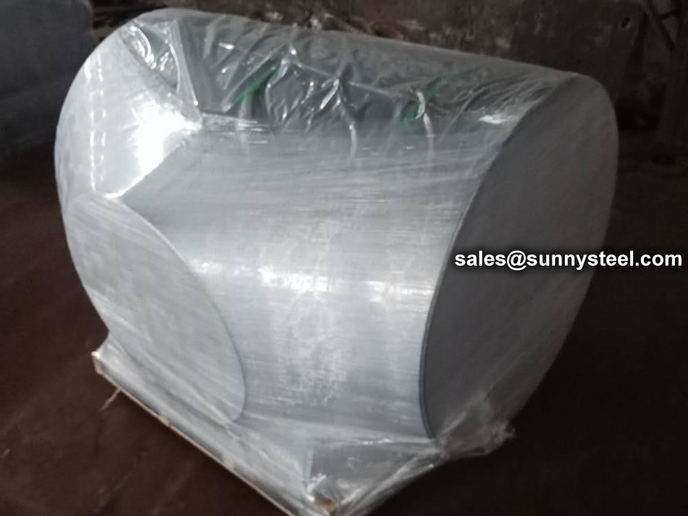
For packing of carbon steel flanges with painting,we would use the bubble wrap to protect the painting.For flanges without painting or oiled with long-term shipment,we would suggest client to use the anti-tarnish paper and plastic bag to prevent the rust.

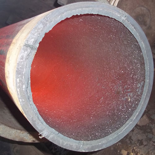
Ceramic lined pipe is made through self-propagating high-temperature synthesis (SHS) technique.
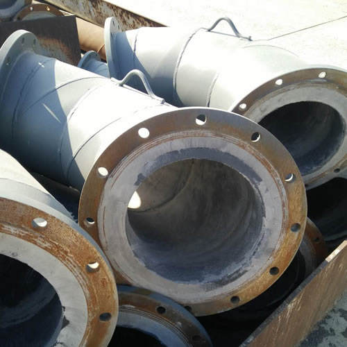
Cast basalt lined steel pipe is composed by lined with cast basalt pipe, outside steel pipe and cement mortar filling between the two layers.
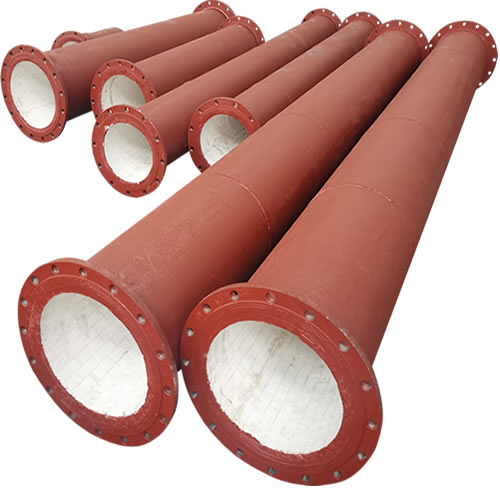
Ceramic tile lined pipes have very uniform coating of specially formulated ceramic material that is affixed to the inner of the pipe.
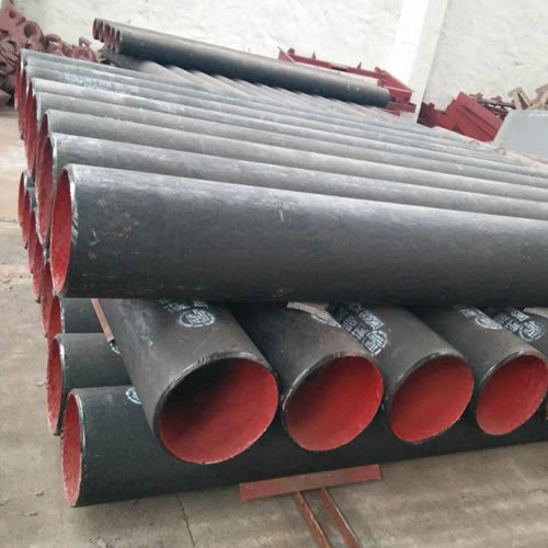
The material of the rare earth alloy wear-resistant pipe is ZG40CrMnMoNiSiRe, which is also the grade of rare earth alloy steel.
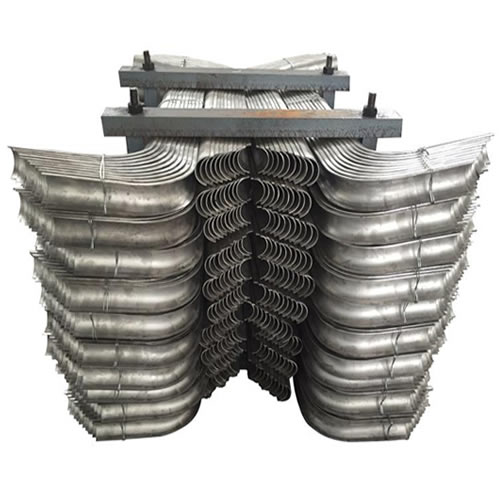
Tubes Erosion Shields are used to protect boiler tubing from the highly erosive effects of high temperatures and pressures thereby greatly extending tube life.
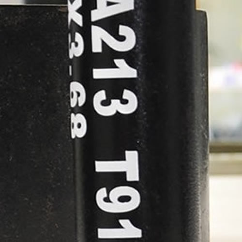
The ASTM A213 T91 seamless tubes are primarily used for boiler, superheater, and heat-exchanger.

When you partner with Sunny Steel, you can stop worrying about meeting deadlines thanks to our responsive and timely service. You'll also say goodbye to unnecessary shopping around. Instead, you'll get white glove service from an expert who understands your needs and can get you the materials you need quickly.